
Motor capable of generating electricity

A technology for generating motors and stators, which is applied to electromechanical devices, electrical components, and electric components, etc., can solve the problems of small power generation, small area of ​​the side wall portion 911, and difficulty, and achieve the effect of improving power generation efficiency.

Active Publication Date: 2013-08-14
SUNONWEALTH ELECTRIC MACHINE IND
View PDF6 Cites 4 Cited by
  • Summary
  • Abstract
  • Description
  • Claims
  • Application Information

AI Technical Summary

Problems solved by technology

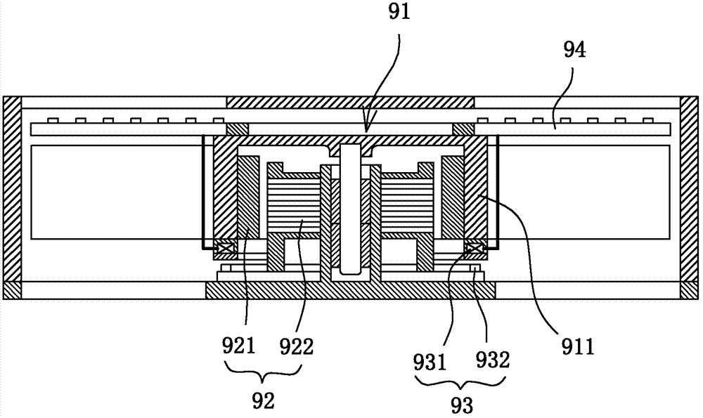
However, under the current trend of motor miniaturization and thinning, the general design will try to reduce the length, width and thickness of each element, and the area of ​​the bottom surface of the side wall part 911 of the existing heat dissipation fan is extremely limited, obviously not enough. It is easy to install the second coil element 931 with a complex winding structure at the bottom surface, and because the bottom surface of the sidewall portion 911 has an extremely small area, even if the second coil element 931 can be arranged on the bottom surface, the second coil Element 931 can only provide a very small amount of power generation

Method used


Image

  • Motor capable of generating electricity
  • Motor capable of generating electricity
  • Motor capable of generating electricity

Examples


Embodiment Construction

[0042] In order to make the above-mentioned and other objects, features and advantages of the present invention more comprehensible, the preferred embodiments of the present invention are specifically cited below, together with the accompanying drawings, as follows:

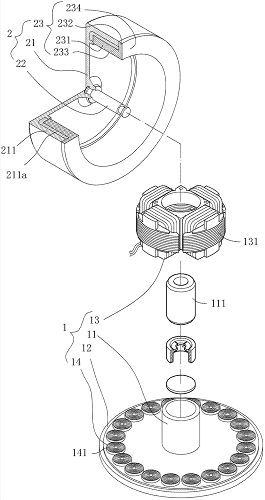
[0043] Please refer to image 3 and Figure 4 , which depicts the first embodiment of the generator-generating motor of the present invention. The generator motor includes a base 1, a rotor 2, a drive circuit 3 and a power unit 4, wherein the rotor 2 is rotatably combined with the base 1, and the drive circuit 3 is combined with the base 1 to generate The driving signal used to drive the rotor 2 is also combined with the base 1 to store or use the power generated during the rotation of the rotor 2 .

[0044] The base 1 has a shaft tube 11 , a bearing surface 12 , a first stator set 13 and a second stator set 14 . The shaft tube 11 accommodates a bearing 111; the bearing surface 12 is located at the periphery o...


PUM


Abstract

A motor with power-generating coil module includes: a base that has a shaft tube, a supporting surface surrounding the shaft tube, a first coil module mounted on an outer circumferential surface of the shaft tube, and a second coil module disposed above the supporting surface; a rotor that has a carrier extending a lateral wall toward the base, a shaft rotatably coupling with the shaft tube, and a magnetic member mounted on the lateral wall and having an axial extension and a radial extension, with a first magnetic face on the axial extension and facing the first coil module and a second magnetic face on the radial extension and facing the second coil module; a driving circuit electrically connecting with one of the first and second coil modules; and a power-storing unit electrically connecting with the other one of the first and second coil modules.

Description

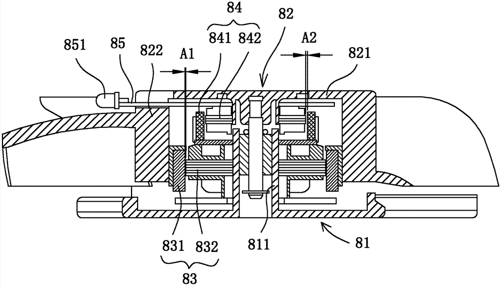
technical field [0001] The invention relates to a generator capable of generating electricity, in particular to a generator capable of generating electricity with a simple structure. Background technique [0002] Please refer to figure 1 As shown, it is a kind of existing heat dissipation fan with power generation function disclosed in the new patent case of China Taiwan Announcement No. M290267 "radiating heat dissipation fan". The heat dissipation fan has a base 81, a fan wheel 82, a The driving unit 83 , a power generating unit 84 and a light emitting unit 85 . The base 81 has a shaft tube 811, the fan wheel 82 is rotatably pivoted to the shaft tube 811, and the fan wheel 82 has a base 821, the edge of the base 821 extends toward the base 81 to form a Ring wall 822; the drive unit 83 includes a first magnet ring 831 and a first coil element 832, the first magnet ring 831 is combined with the inner peripheral wall of the ring wall 822 of the fan wheel 82, and the first c...

Claims


Application Information

Patent Timeline
Patent Type & Authority Applications(China)
IPC IPC(8): H02K21/14H02K1/27
CPCH02K21/222H02K16/04H02K1/27H02K21/24H02K11/0094H02K21/14H02K16/00F04D25/064F04D25/0646
Inventor 洪银树
Owner SUNONWEALTH ELECTRIC MACHINE IND
Learn More