Automatic horizontal boring and milling machine

A milling and boring machine, horizontal technology, applied in the field of automatic horizontal milling and boring machines, can solve the problems of low processing efficiency, machine axis can not be automatically positioned, cumbersome operation, etc., to improve reliability, reduce machine failure rate, and simplify the operation process requirements Effect

Inactive Publication Date: 2013-08-21
SHENYANG MASCH TOOL CO LTD
View PDF5 Cites 14 Cited by
  • Summary
  • Abstract
  • Description
  • Claims
  • Application Information

AI Technical Summary

Problems solved by technology

The disadvantage of this control method is that the axis of the machine tool cannot be positioned automatically, and the pro

Method used


Image

  • Automatic horizontal boring and milling machine
  • Automatic horizontal boring and milling machine
  • Automatic horizontal boring and milling machine

Examples


Example Embodiment

[0027] Example 1

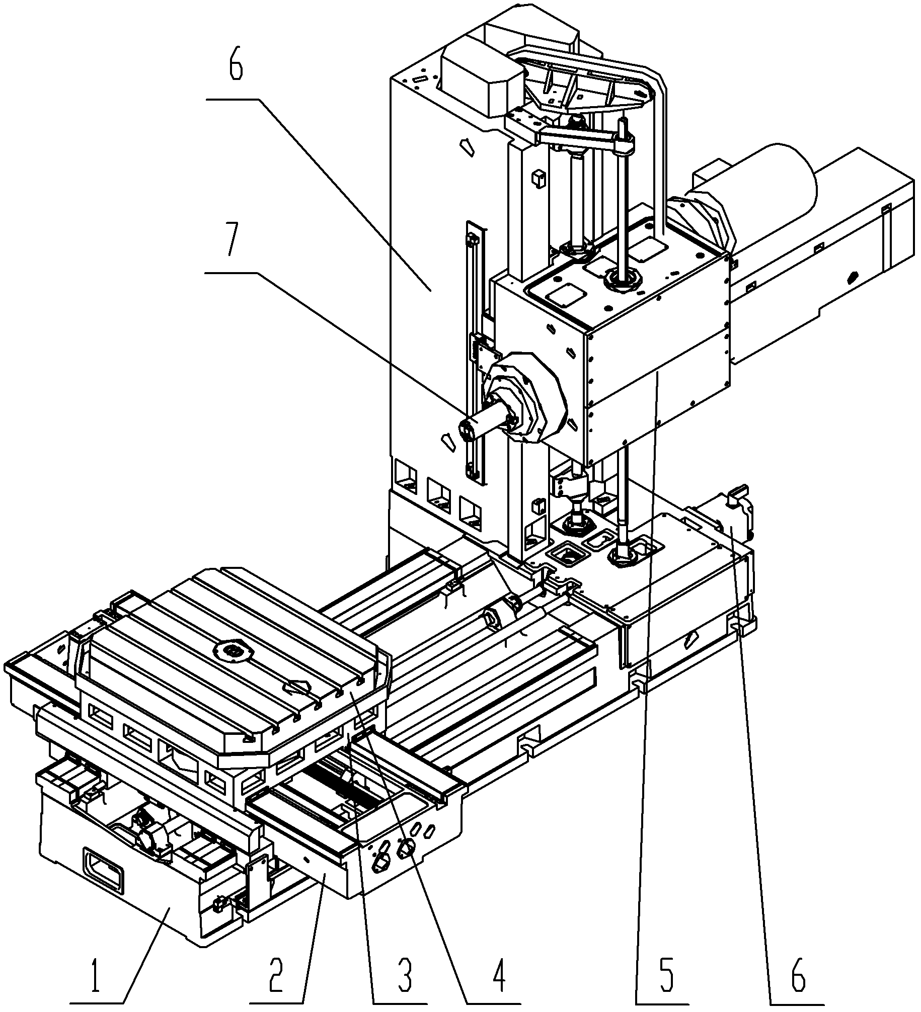
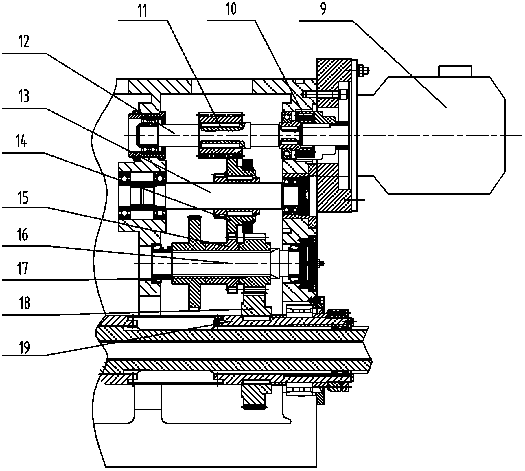
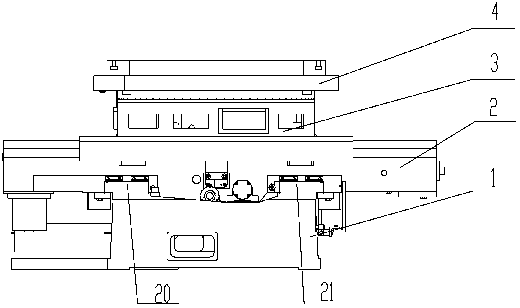
[0028] AH90 automatic horizontal milling and boring machine, including bed 1, lower slide 2, upper slide 3, worktable 4, spindle box 5, column 6, boring shaft 7, feed servo motor 8 and electrical system, such as figure 1 As shown, the column 6 is fixed on the bed 1, the spindle box 5 is installed on the column 6, and the spindle box 5 can move up and down on the column 6 (Y-axis movement); the sliding seat 2 is installed on the guide rail of the bed 1, The lower seat 2 can move longitudinally on the bed 1 (Z-axis movement); the upper slide 3 is installed on the lower seat 2, and the upper slide 3 can move laterally on the lower seat 2 (X-axis movement); the workbench 4 is installed on the upper slide 3, the workbench 4 can rotate on the upper slide 3 (B-axis movement), the feed motor 8 is installed on the bed 1, the boring shaft 7 is in the headstock 5, and can be Telescoping (W-axis movement) in the headstock 5. In the main shaft box 5, there is a main sh...

Example Embodiment

[0039] Example 2

[0040] An automatic horizontal milling and boring machine (we call it AH90 automatic horizontal milling and boring machine), the automatic horizontal milling and boring machine is specifically composed of the following parts: bed 1, lower slide 2, upper slide 3, working Table 4, spindle box 5, column 6, boring shaft 7, feed servo motor 8, guide rail, electrical system; wherein: the lower slide 2 is arranged on the bed 1, the upper slide 3 is arranged above the slide 2 and both Connected together; the workbench 4 is arranged on the upper slide 3; a feed servo motor 8 and a column 6 are provided at the proximal end of the horizontally arranged bed 1, and the vertically arranged column 6 is distributed near the bed 1 The proximal end of that end of the box 9 is arranged; the spindle box 5 is arranged on the column 6 and can move up and down relative to the column 6; the boring shaft 7 is arranged on the spindle box 5 and its axial direction is arranged along th...

Example Embodiment

[0050] Example 3

[0051] The content of this embodiment is basically the same as that of Embodiment 2, and its difference mainly lies in:

[0052] 1) The workbench clamping mechanism provided between the upper sliding seat 3 and the workbench 4 adopts other clamping and anti-loosening gap adjustment structures.

[0053] 2) The basic functions of the electrical system described above are similar to those in Embodiment 2, but other specific configurations are selected.


PUM


Abstract

The invention discloses an automatic horizontal boring and milling machine which is mainly composed of a machine body (1), a lower sliding seat (2), an upper sliding seat (3), a workbench (4), a spindle box (5), a vertical post (6), a boring shaft (7), a feeding servo motor (8), a guide rail and an electric system, wherein the machine body (1) is provided with two guide rails, namely, a guide rail A (20) and a guide rail B (21), both of which have the same horizontal height and are in parallel arrangement; a workbench clamping mechanism is also arranged between the upper sliding seat (3) and the workbench (4); the workbench clamping mechanism is specifically composed of a hydraulic cylinder (24), a piston (25), a disc spring (26), a piston rod (27) and a round gasket (28). The automatic horizontal boring and milling machine has a simplified structure, low fault rate, high machining precision, clamping reliability of the workbench and expectable huge economic value and social value.

Description

technical field [0001] The invention relates to the technical field of machine tool structure design and application, and in particular provides an automatic horizontal milling and boring machine. Background technique [0002] In the prior art, the horizontal milling and boring machine is a universal machine tool; it can perform drilling, boring, reaming, reaming, countersinking, milling, and threading on large parts such as boxes, shells, and machine bases. Machining operations. Horizontal milling and boring machines are widely used in energy, transportation, heavy-duty, petrochemical machinery and other industries. For box parts, horizontal milling and boring machines are a commonly used key equipment. [0003] Ordinary horizontal milling and boring machines use ordinary motors as the power source, and control the position change of the sliding transmission gear through the hydraulic-mechanical linkage device to obtain different speeds and feed rates. The internal struct...

Claims


Application Information

Patent Timeline
IPC IPC(8): B23B39/02B23Q5/16B23Q5/36B23Q1/26
Inventor 易刚王显春邓开楠钱颖娟韩涛王桂玲叶龙张文生杨小娟
Owner SHENYANG MASCH TOOL CO LTD
Why Eureka
Try Eureka