Brake actuator

A technology of brake control and brake equipment, applied in the direction of brakes, brake action starting devices, transportation and packaging, etc., can solve the problems of control device structure consumption, etc., and achieve improved dynamic and adjustment technology, high braking effect, and improved The effect of error proofing

Inactive Publication Date: 2013-08-21
IPGATE
View PDF7 Cites 19 Cited by
  • Summary
  • Abstract
  • Description
  • Claims
  • Application Information

AI Technical Summary

Problems solved by technology

An inlet valve and an outlet valve are respectively assigned to the wheel brakes

Method used


Image

  • Brake actuator

Examples


Embodiment Construction

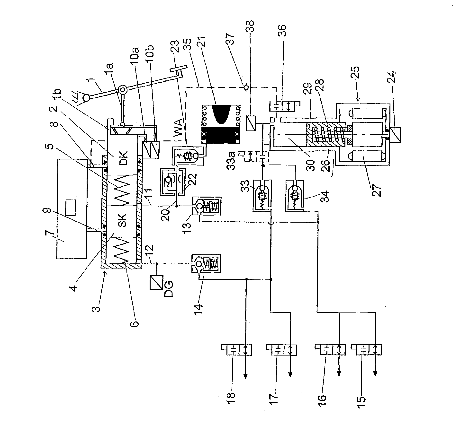
[0013] The brake actuating device shown in the single figure has an actuating device, in particular a pivotably mounted brake pedal 1 , which acts via a spring device or elastic member on the side of a first piston-cylinder arrangement 3 First piston 2 on. The first piston-cylinder arrangement 3 has a further piston 4 between which a spring 5 or 6 is arranged respectively between the bottom of the first piston-cylinder arrangement and the piston 4 . The storage container 7 is connected via hydraulic lines 8 , 9 to the working chamber formed by the pistons 2 , 4 . The piston-cylinder unit shown here is therefore characterized by a tandem master brake cylinder which can advantageously be provided with a so-called central valve. A so-called twin-configuration arrangement of the pistons or cylinders, ie parallel next to each other, is expedient if the structural length is decisive. Preferably, the movement of the first piston 2 can be determined by means of in particular redunda...


PUM


Abstract

The invention relates to a brake actuator, with an actuating device, in particular a brake pedal, a travel simulator, a first piston-cylinder device, which is connected to at least one wheel brake via a first hydraulic connection piece provided with a first valve means, and an electric motor driven amplifier means. The electric motor driven amplifier means comprises a second piston-cylinder means which is connected to the wheel brake through a second hydraulic connection piece provided with a second valve means and which is connected to a storage device through a third hydraulic connection piece provided with a third valve means. The invention brings forward that the first valve means comprises an entry switching valve/exit switching valve associated with the wheel brake and operated in the multiplex mode.

Description

technical field [0001] The invention relates to a brake actuation device for a motor vehicle. Background technique [0002] A brake actuation device of the type mentioned at the outset is known from DE 10 2010 040 097 A1. Various advantages can already be achieved with such a brake actuation device, such as compact design and functional integration, elimination of the pump and the associated noise, weight reduction and high dynamics. In this arrangement, an inlet valve and an outlet valve are respectively assigned to the wheel brakes, so that the actuating device is relatively complex in construction. Contents of the invention [0003] It is therefore the object of the present invention to provide a brake actuation device of the type mentioned at the outset, which is relatively inexpensive in terms of structural complexity while maintaining the advantages. [0004] The object of the invention is achieved by means of a brake actuation device according to the invention, wh...

Claims


Application Information

Patent Timeline
IPC IPC(8): B60T8/40
CPCB60T7/042B60T13/146B60T13/74B60T8/40B60T8/4081
Inventor 海因茨·莱贝尔
Owner IPGATE
Why Eureka
Try Eureka