


Quick Research
Generate reliable direction feasibility study reports for your R&D in just a few steps.

Technical Q&A
Discover and master advanced knowledge NOW. Basics, ideas, possibilities, all at once.

Find Solutions
As an expert in R&D theories, this can generate solutions to your technical problems instantly.

Evaluate Feasibility
Analyze your overall solution with one click, know your potential R&D risks in advance.

Monitor Landscape
Get weekly tech updates, stay abreast of the latest tech innovations and key insights.
System and method for compensating cetan
A technology for hexadecane and fuel injection, applied in the field of systems and methods for compensating hexadecane, can solve the problems of increasing engine hydrocarbon emissions and particulate matter, and achieve the effects of reducing noise and reducing emissions
- Summary
- Abstract
- Description
- Claims
- Application Information
AI Technical Summary
Problems solved by technology
Method used
Image

Examples
Embodiment Construction
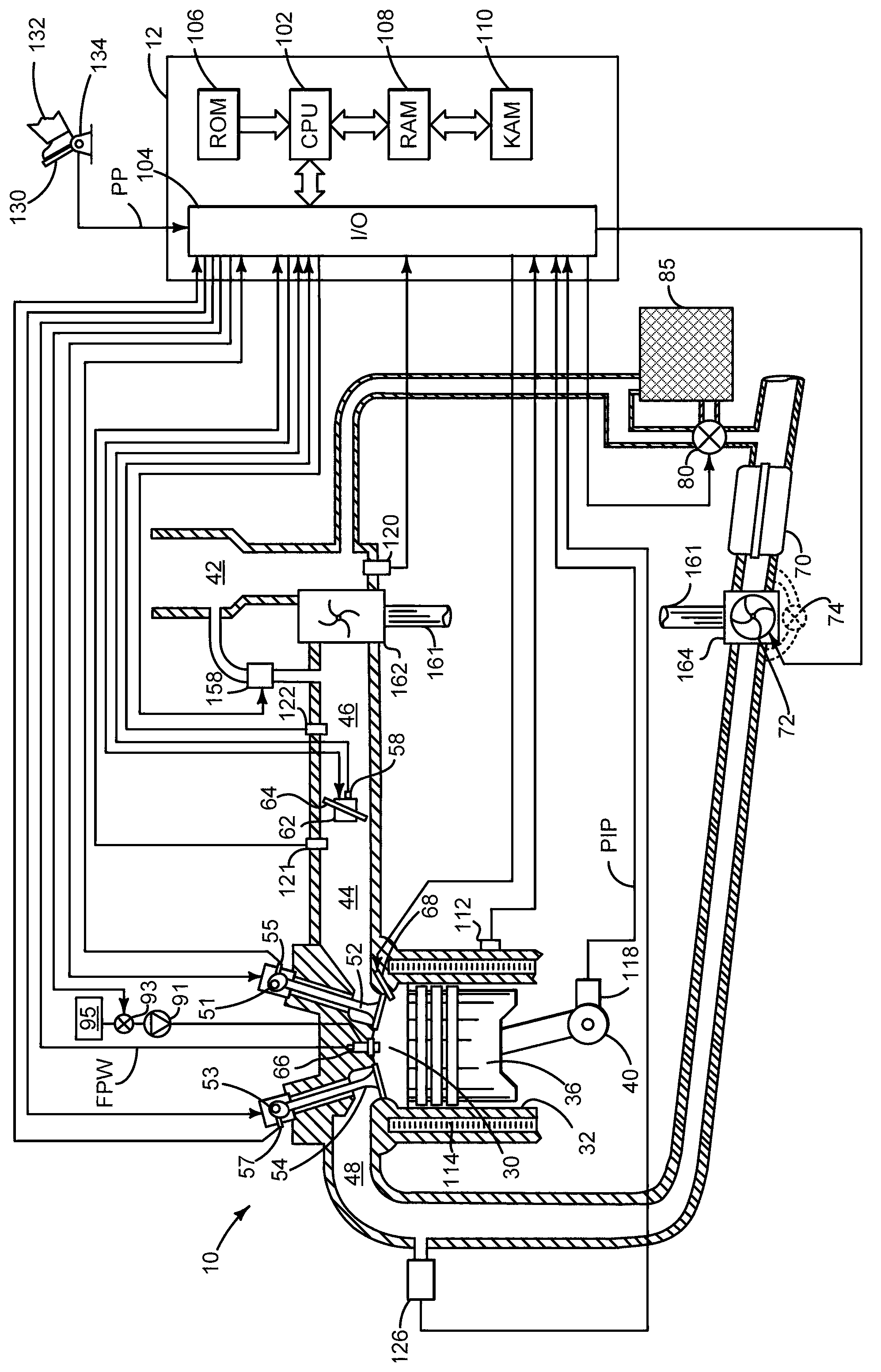
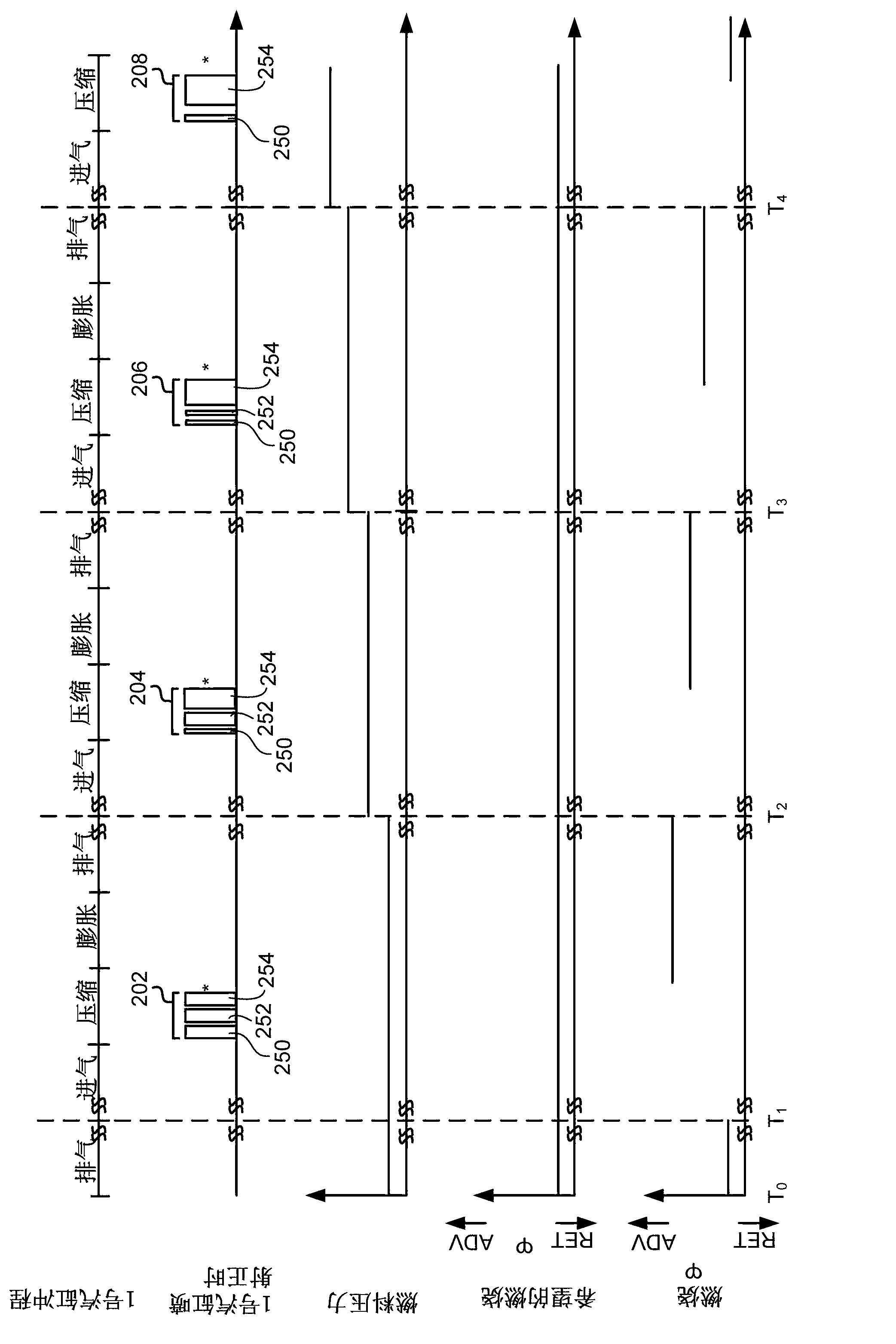
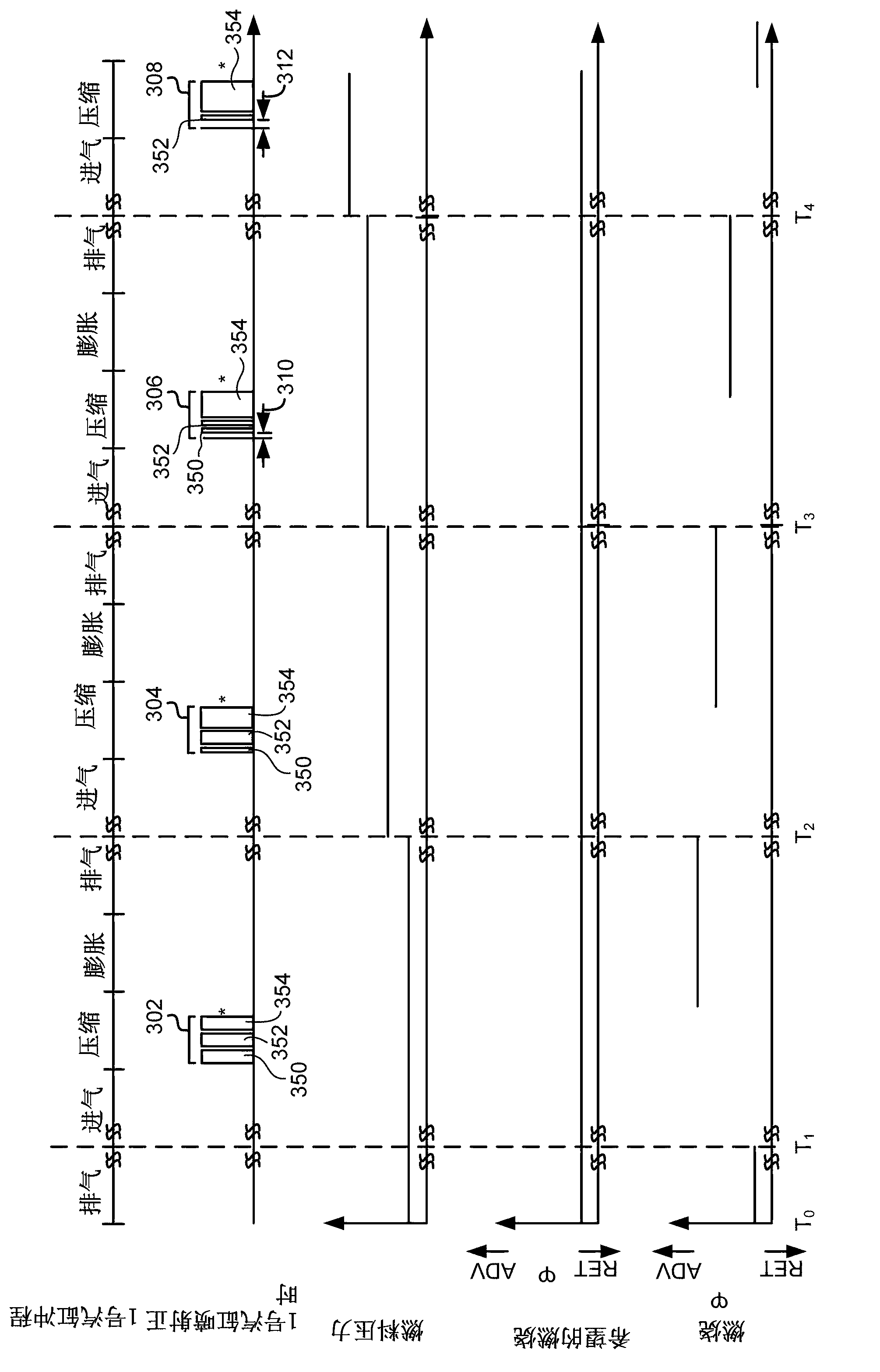
[0023] The present invention relates to compensating for the combustion of fuels having different cetane numbers. figure 1 shows an example of a supercharged diesel engine in which Figure 7-8 A method to adjust fuel injection to improve engine emissions and / or reduce combustion noise. Figure 2-6 An example of simulating fuel injection timing to compensate for burning fuels with different cetane numbers is shown.
[0024] refer to figure 1 , an internal combustion engine 10 comprising a plurality of cylinders— figure 1 One of the cylinders is shown - controlled by the electronic engine controller 12 . Engine 10 includes combustion chamber 30 and cylinder walls 32 with piston 36 disposed therein and connected to crankshaft 40 . Combustion chamber 30 is shown communicating with intake manifold 44 and exhaust manifold 48 via respective intake valve 52 and exhaust valve 54 . The intake and exhaust valves may each be operated by an intake cam 51 and an exhaust cam 53 . The p...
PUM
 Abstract
Description
Claims
Application Information
 - R&D Engineer
- R&D Manager
- IP Professional
- Industry Leading Data Capabilities
- Powerful AI technology
- Patent DNA Extraction
Browse by: Latest US Patents, China's latest patents, Technical Efficacy Thesaurus, Application Domain, Technology Topic, Popular Technical Reports.
© 2024 PatSnap. All rights reserved.Legal|Privacy policy|Modern Slavery Act Transparency Statement|Sitemap|About US| Contact US: help@patsnap.com