Water-cooled gas laser tube

A gas laser, water-cooled technology, used in gas laser parts, laser parts and other directions, can solve the problems of fragile customers, loss, inconvenient recycling and reuse, and achieve the effect of solid overall structure and convenient assembly.

Inactive Publication Date: 2013-08-21
HANGZHOU XINTOU TECH
View PDF3 Cites 10 Cited by
  • Summary
  • Abstract
  • Description
  • Claims
  • Application Information

AI Technical Summary

Problems solved by technology

[0005] The invention provides a water-cooled gas laser tube that is easy to recycle and reuse, which solves the problems that the existing glass-structured laser tube is easily broken and causes losses to customers, it is not easy to recycle and reuse, and a large amount of harmful gas will be generated in the production process.
By designing a metal support frame and placing the gas storage chamber of the discharge tube in the support frame, it is not easy to be damaged during transportation; by designing the insulating anode chamber to be connected with one end of the discharge tube, and placing the reflector and anode inside it to solve the problem Solve the insulation problem between the high-voltage anode and the metal support frame, so that the support frame can be made of high-strength metal materials

Method used


Image

  • Water-cooled gas laser tube
  • Water-cooled gas laser tube

Examples


Embodiment 1

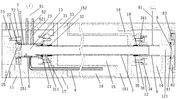
[0019] Embodiment one, see figure 1 , an air-cooled gas laser tube, including a support frame 1, a discharge tube 3, an anode 5, a cathode 6, a mirror 7 and an output mirror 8.

[0020] The support frame 1 is made of metal material. The support frame 1 is a straight rod-shaped structure. The left end of the support frame 1 is provided with an anode cover 11 , and the right end of the support frame 1 is provided with a cathode cover 12 . The cathode cover 12 and the support frame 1 enclose a cathode chamber 14 . Both the anode cover 11 and the cathode cover 12 are made of metal materials. An anode chamber 13 surrounded by an insulating sleeve 2 and an insulating cover 25 is provided in the space enclosed by the anode cover 11 and the metal support frame 1 .

[0021] The support frame 1 is provided with a cooling chamber 15 and an air storage chamber 16 . The cooling chamber 15 extends in the left-right direction. The right end of the cooling chamber 15 is provided with a ...

Embodiment 2

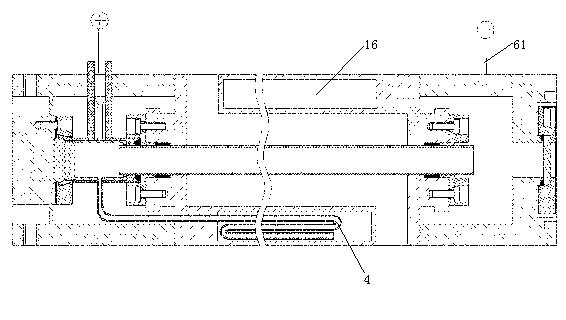
[0040] Embodiment two, see figure 2 , the difference with Embodiment 1 is:

[0041] In order to prolong the time for the laser gas to flow back into the discharge tube 3, so that the laser gas can have sufficient time to regenerate and recover, the part of the gas return pipe 4 located in the gas storage chamber 16 is designed in a circuitous and bent structure. The cathode is not designed, but the cathode power line 61 is directly electrically connected to the cathode cover 12 .


PUM


Abstract

The invention relates to a gas laser tube. A water-cooled gas laser tube comprises a discharge tube, a cathode electrode, an anode electrode, a reflecting mirror, an output mirror, a metal supporting frame, an insulated anode electrode chamber and a cathode electrode chamber. The anode electrode chamber is connected at one end of the metal supporting frame, and the cathode electrode chamber is connected at the other end of the metal supporting frame. The metal supporting frame is provided with a cooling chamber and a gas storage chamber. The cooling chamber extends in the extension direction of the discharge tube, and the gas storage chamber is communicated with both the anode electrode chamber and the cathode electrode chamber. The discharge tube penetrates through the cooling chamber and communicates the anode electrode chamber with the cathode electrode chamber together , the two ends of the discharge tube are connected with the cooling chamber in a sealing mode, a water inlet is formed at one end of the cooling chamber, a water outlet is formed at the other end of the cooling chamber, the reflecting mirror and the anode electrode are located in the anode electrode chamber, the output mirror and the cathode electrode are located in the cathode electrode chamber. The water-cooled gas laser tube can be conveniently recycled and reused and solves the problems that an existing laser tube of a glass structure can be easily broken to caused losses to clients, is inconveniently to recycle and reuse and a large amount of harmful gas can be generated in the process of production.

Description

technical field [0001] The invention relates to a gas laser tube, in particular to a water-cooled gas laser tube. Background technique [0002] The existing gas laser tubes are all in the form of a sealed structure, that is, including a discharge tube, a water-cooled tube sleeved outside the discharge tube, a gas storage tube sleeved outside the water-cooled tube, electrodes and resonant cavity mirrors (including reflectors and Output mirror), the discharge tube, water cooling tube and gas storage tube are all glass tubes, the water cooling tube and the discharge tube, and the discharge tube and the gas storage tube are all welded together by high-temperature flame firing to form a cooling chamber and a gas storage tube The gas storage chamber communicates with both ends of the discharge tube, and the gas storage chamber is filled with laser gas. [0003] The existing gas laser tubes have the following disadvantages: since the glass tubes are connected together by sinte...

Claims


Application Information

Patent Timeline
Patent Type & Authority Applications(China)
IPC IPC(8): H01S3/02H01S3/03
Inventor 陈海榕李鹤群
Owner HANGZHOU XINTOU TECH
Why Eureka
Try Eureka