busbar system

A busbar and flowbar technology, which is applied in the installation of electrical components, busbars, cables, etc., can solve problems such as size design restrictions, achieve good heat flow, save materials and components, and save materials and structural components.

Active Publication Date: 2017-10-03
SIEMENS AG
View PDF6 Cites 0 Cited by
  • Summary
  • Abstract
  • Description
  • Claims
  • Application Information

AI Technical Summary

Problems solved by technology

[0003] The housings of conventional busbar systems form a functional unit with the busbars, which creates restrictions in terms of dimensioning the busbar elements and in terms of ventilation of the system

Method used


Image

  • busbar system
  • busbar system
  • busbar system

Examples


Embodiment Construction

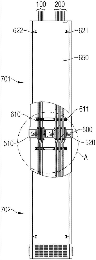
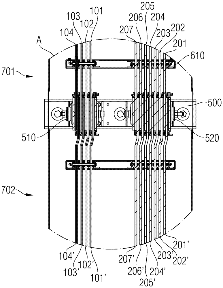
[0025] Figure 1A The first perspective view of the busbar system as a top view shows the busbar system for conveying electrical energy. The busbar system comprises a first segment 701 and a second segment 702 . The segments 701, 702 respectively comprise first busbars 101, 102, 103, 104 with a first cross-section and a holder 500, 501, wherein the busbars of the corresponding segments 701, 702 are held by the corresponding holders 500, 501 and are electrically connected to each other through connecting mechanisms 510, 520. according to Figure 1A , the holder 500 is assigned to the first segment 701 and the holder 501 is assigned to the second segment 702 . The connection means 510, 520 connect the respective first busbars 101, 102, 103, 104 of the first and second segments.

[0026] The busbars of the busbar system according to the invention are elongated in the direction of current flow. according to Figure 1A In the schematic diagram in , this means that the current fl...


PUM


Abstract

A busbar system for conveying electrical energy is disclosed, wherein the busbar system comprises at least a first segment and a second segment, wherein the segments each comprise at least one first busbar having a first cross-section and holders, wherein the busbars of the segments are held by corresponding holders and are electrically connected to each other through connection mechanisms.

Description

technical field [0001] The invention relates to a busbar system for conveying electrical energy. Background technique [0002] The electrical distribution system can be configured as a busbar system. Busbar systems are used for conveying and distributing electrical energy. Typical tasks of busbar systems are, for example, the connection of transformers to secondary distributors via the main distributor or the supply of large consumers. Busbar systems are likewise used in wind energy installations to conduct the current generated by the generator at the top of the tower to the bottom of the tower. The busbars of a busbar system are typically accommodated in a busbar box, which prevents unwanted electrical contact between the busbars and the environment. In this case, the busbar box is dimensioned such that on the one hand a distance is maintained to prevent undesired electrical contact and on the other hand the busbars inside the busbar box are cooled by natural or forced ...

Claims


Application Information

Patent Timeline
Patent Type & Authority Patents(China)
IPC IPC(8): H02G5/00
CPCH02G3/0493H02G5/025H02G5/06Y02E10/72
Inventor F.阿勒费尔德R.哈尔
Owner SIEMENS AG
Why Eureka
Try Eureka