Blind buried orifice plate laminating method and blind buried orifice plate manufactured with blind buried orifice plate laminating method

A blind and buried via board and substrate technology, which is used in the manufacture of multilayer circuits, the structural connection of printed circuits, and the formation of electrical connections of printed components. Accuracy and other issues, to achieve the effect of thermal stress balance, warpage improvement, and accuracy improvement

Active Publication Date: 2013-08-21
MEIZHOU ZHIHAO ELECTRONICS TECH
View PDF11 Cites 4 Cited by
  • Summary
  • Abstract
  • Description
  • Claims
  • Application Information

AI Technical Summary

Problems solved by technology

Since there are certain differences in the thickness, copper content and conductive pattern of the two boards during the second pressing, the thermal stress generated by the heating of the two boards is quite different during

Method used


Image

  • Blind buried orifice plate laminating method and blind buried orifice plate manufactured with blind buried orifice plate laminating method
  • Blind buried orifice plate laminating method and blind buried orifice plate manufactured with blind buried orifice plate laminating method
  • Blind buried orifice plate laminating method and blind buried orifice plate manufactured with blind buried orifice plate laminating method

Examples


Embodiment Construction

[0018] The following will clearly and completely describe the technical solutions in the embodiments of the present invention. Obviously, the described embodiments are only some of the embodiments of the present invention, rather than all the embodiments. Based on the embodiments of the present invention, all other embodiments obtained by persons of ordinary skill in the art without making creative efforts belong to the protection scope of the present invention.

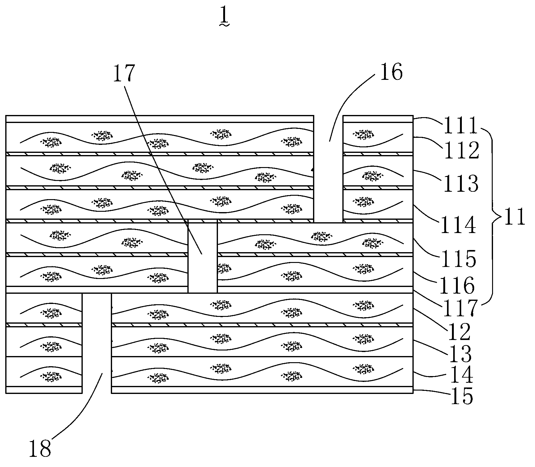
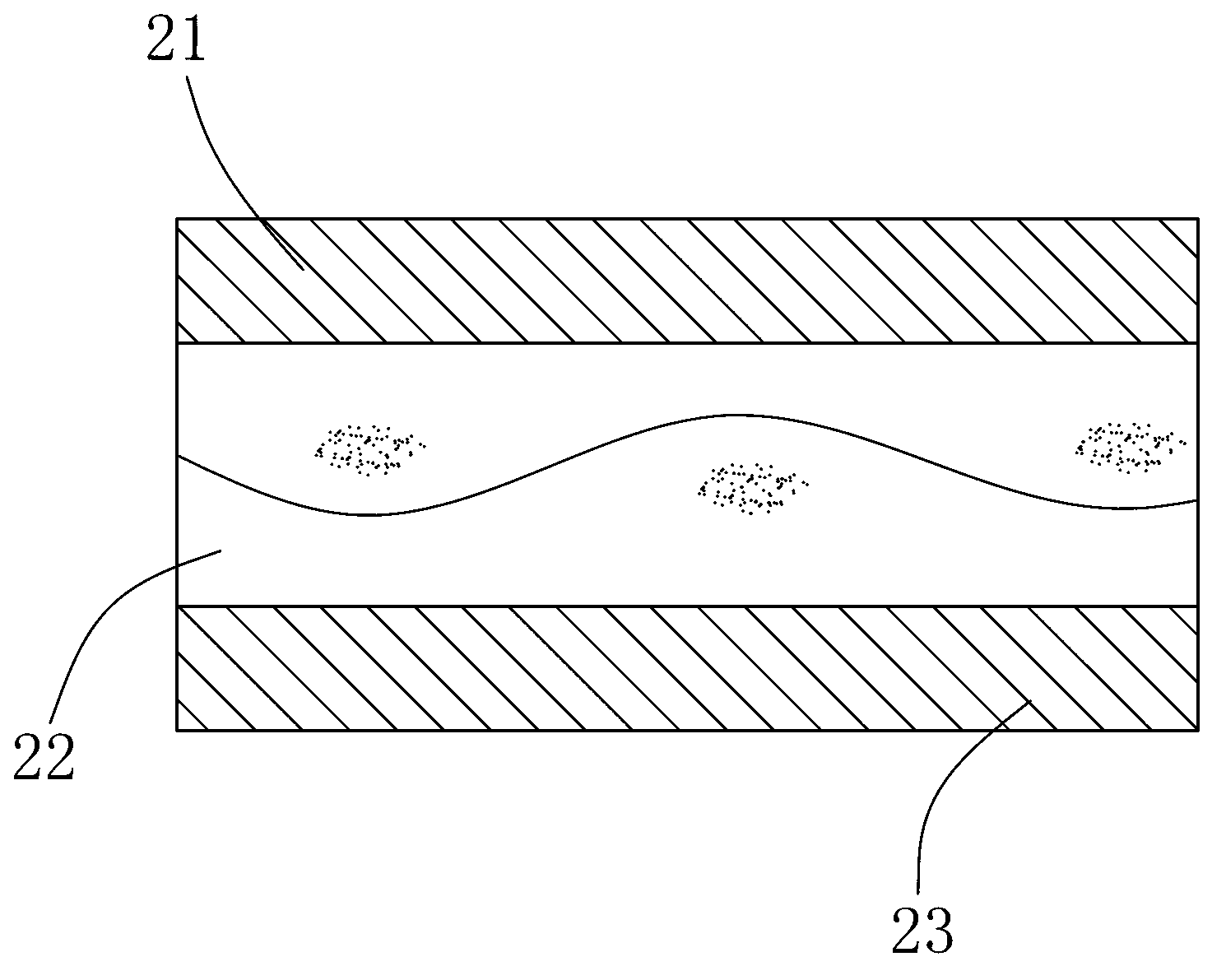
[0019] Please refer to figure 1 , is a side cross-sectional view of a preferred embodiment of the blind buried plate of the present invention. The blind and buried via plate 1 includes a first substrate 11 , a second substrate 13 and a first circuit layer 15 which are superimposed on each other. The second substrate 13 is sandwiched between the first substrate 11 and the first circuit layer 15 . The first substrate 11 and the second substrate 13 are separated by a first insulating layer 12 . The second substrate 1...


PUM


Abstract

The invention discloses a blind buried orifice plate laminating method and a blind buried orifice plate manufactured with the blind buried orifice plate laminating method. The blind buried orifice plate laminating method includes the following steps. First copper foil, a first semi-solidified piece, a first circuit board, a second semi-solidified piece, a second circuit board, a third semi-solidified piece and second copper foil are sequentially stacked up and laminated for the first time, drilled and undergo hole metallization treatment. Circuits are manufactured on the first copper foil and the second copper foil and a first substrate is formed. A second substrate with a single-layer conductive circuit is provided. The first substrate, a fourth semi-solidified piece, the second substrate, a fifth semi-solidified piece and third copper foil are sequentially stacked up and laminated for the second time and a multiple-layer plate is obtained, drilled and undergo hole metallization treatment. Circuits are manufactured on the third copper foil. The blind buried orifice plate is formed. The laminating method and the blind buried orifice plate manufactured with the laminating method effectively solve the problem that products are disqualified as a large warping degree occurs during the process of laminating blind buried orifice plates in a hot mode.

Description

technical field [0001] The invention relates to the processing technology of multi-layer boards, in particular to a pressing method for a blind-buried hole board and a blind-buried hole board prepared by the pressing method. Background technique [0002] In the printed circuit board industry, the blind buried hole board uses the process of drilling and metallization in the hole to achieve electrical connection between the layers of the circuit, which is a conventional multi-layer circuit board structure. When carrying out lamination of a multi-layer blind buried hole board, it is first necessary to carry out the first lamination of two double-sided circuit boards, then perform drilling, hole metallization and double-sided circuit fabrication to form the first substrate, and finally Then the first substrate and the third double-sided circuit board are pressed together for the second time. Since there are certain differences in the thickness, copper content and conductive pat...

Claims


Application Information

Patent Timeline
IPC IPC(8): H05K1/14H05K3/42H05K3/46
Inventor 林人道刘喜科戴晖
Owner MEIZHOU ZHIHAO ELECTRONICS TECH
Why Eureka
Try Eureka