Bonding method and members to be bonded

A technology for joining components and joining methods, which is applied in welding equipment, engine components, manufacturing tools, etc., and can solve problems such as difficulty in obtaining joint strength and uneven heating

Inactive Publication Date: 2013-08-21
NISSAN MOTOR CO LTD
View PDF9 Cites 12 Cited by
  • Summary
  • Abstract
  • Description
  • Claims
  • Application Information

AI Technical Summary

Problems solved by technology

[0006] However, the current used to cause resistance heating concentrates on the high surface pressure portion of the joint surface between the members to be joined, and does not flow uniformly throughout the entire contact surface, resulting in uneven heating, which can only be performed in a limited area and shape. join
For example, there is a problem that, when the joining surfaces of the members to be joined are not on the same plane, it is difficult to uniformly join all the joining surfaces, and it is difficult to obtain stable joint strength.

Method used


Image

  • Bonding method and members to be bonded
  • Bonding method and members to be bonded
  • Bonding method and members to be bonded

Examples


Embodiment approach 1

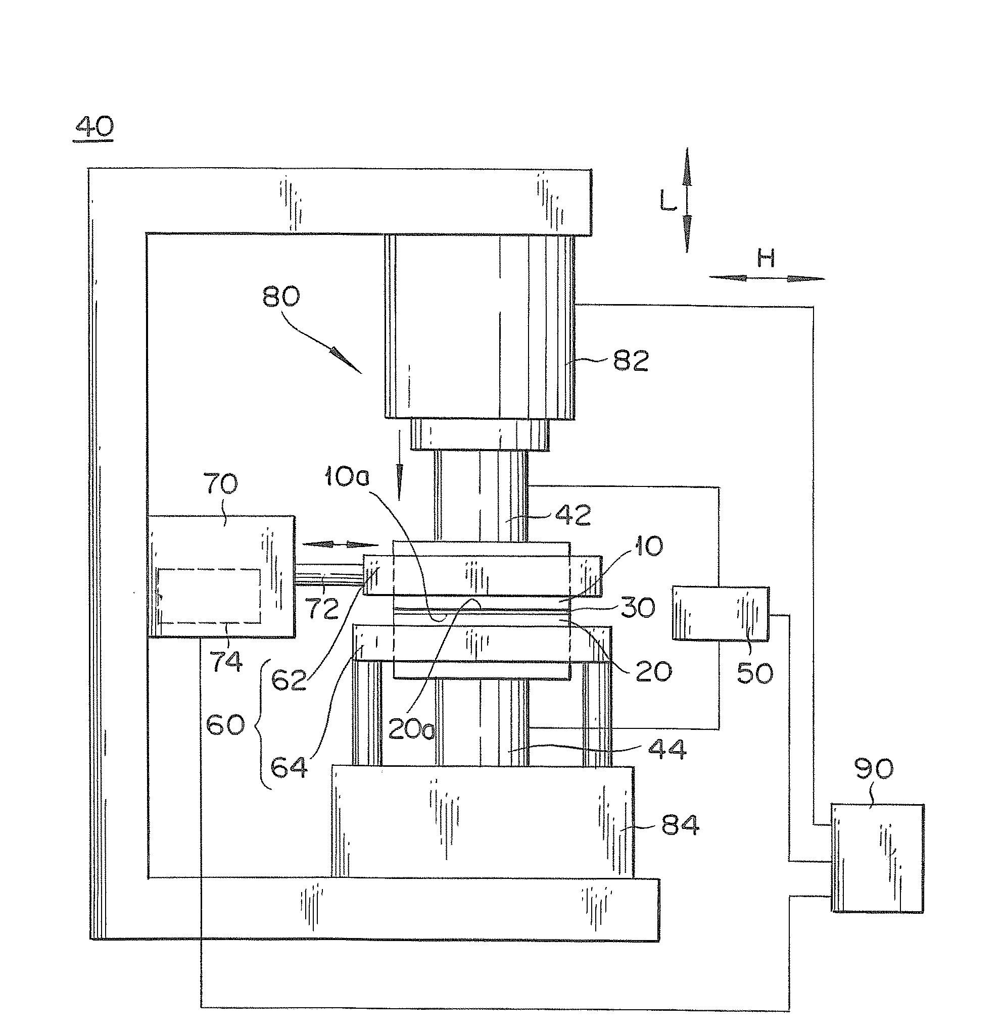
[0028] The joining device 40 according to Embodiment 1 is a joining device for joining a pair of conductive members 10 and 20 to be joined together. Roughly speaking, the bonding device 40 has a bonding member that makes a pair of the bonded members 10, 20 While sliding relative to each other, current flows from one of the member to be joined 10 and the member to be joined 20 to the other via the first electrode 42 and the second electrode 44 to carry out resistance heating, so that the joint surface 10a, the joint The faces 20a are bonded to each other. The joining part utilizing resistance heating and frictional heat (plastic flow) has: a pressing device 80 for pressing the joined member 10 and the joined member 20 against each other; a sliding device 70 for making the joined member 10 , the joined member 20 relatively slides; the current supply device 50, which is used to make the current flow from one of the joined member 10 and the joined member 20 to the other via the e...

Embodiment approach 2

[0077] The joining device 200 according to Embodiment 2 is used to simultaneously join together a workpiece W composed of three or more members to be joined, the three or more members to be joined being made of a conductive material, by using resistance heating and frictional heat. It includes a first electrode 202 , a second electrode 204 , a current supply device 210 , a holding device 220 , a sliding device (sliding member) 230 , a pressurizing device 240 , and a control device 250 .

[0078] The workpiece W is composed of a first joined member 260 located above, a second joined member 270 located below, and an intermediate member as a third joined member disposed between the first joined member 260 and the second joined member 270 . 280 structure, it is possible to easily form a structure in which members to be joined are joined in series. The intermediate member 280 has a first engaging surface 282 in contact with the first engaged member 260 and a second engaging surface...


PUM

PropertyMeasurementUnit
thicknessaaaaaaaaaa

Abstract

Provided is a bonding method for bonding a pair of members to be bonded (10, 20) that comprise a conductive material and have bonding surfaces which are not on identical flat surfaces, said bonding method including a bonding step in which the bonding surfaces (10a, 20a) of the members to be bonded to each other face each other, an electric current is passed from one of the members to be bonded to the other to perform resistance heating while the pair of members to be bonded are slid relative to each other, and the bonding surfaces are bonded to each other. Cut surfaces (120), which are for forming hollow passages (110, 111) and extend along the axes of the hollow passages, are set as the bonding surfaces which are not on identical flat surfaces.

Description

technical field [0001] The present invention relates to a joining method using resistance heating and vibration friction and a joined member applied to the method. Background technique [0002] Conventionally, resistance welding has been used as a method of joining conductive metal materials to each other. Resistance welding is a method in which conductive metal materials are sandwiched between electrodes in a state where the conductive metal materials are in contact with each other, a current is supplied from the electrodes, and the conductive metal is heated by resistance heating due to the contact resistance of the joint surface. The materials are fusion bonded to each other. For example, Patent Document 1 describes a method of vibrating a pair of conductive metal materials to be joined in contact, peeling off the insulating coating on the surface, stopping the vibration, and performing fusion joining by resistance heating. [0003] Prior art literature [0004] patent...

Claims


Application Information

Patent Timeline
Patent Type & Authority Applications(China)
IPC IPC(8): B23K20/00B23K20/24B23K28/02F02F1/24B23K11/11B23K11/12B23K20/10
CPCB23K11/093B23K20/10B23K28/02F02F2200/00F02F1/24B23K11/002
Inventor 水野秀昭深见彻牛岛研史
Owner NISSAN MOTOR CO LTD
Why Eureka
Try Eureka