

Composite push-out mould for punching puncture
A mold and ejection technology, applied in metal processing and other directions, can solve the problems of high production cost, high labor intensity, unreasonable design, etc., and achieve the effect of simple structure, reduced production process, and convenient implementation.
- Summary
- Abstract
- Description
- Claims
- Application Information
AI Technical Summary
Problems solved by technology
Method used
Image

Examples
Embodiment Construction
[0026] In order to deepen the understanding of the present invention, the compound ejection die for punching and piercing of the present invention will be further described in detail below in conjunction with the embodiments and accompanying drawings.
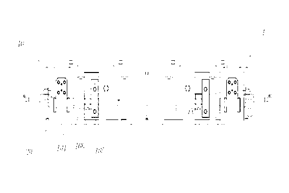
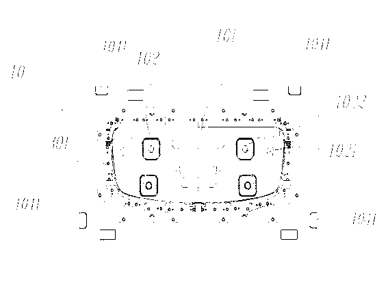
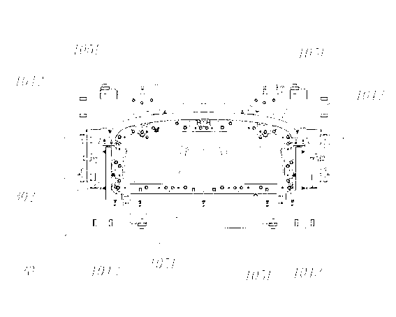
[0027] Figure 1 to Figure 5 A punching and punching compound ejection die according to an embodiment of the present invention is schematically shown. This embodiment is only used to explain the present invention, and does not constitute a limitation to the protection scope of the present invention.
[0028] Such as Figure 1 to Figure 3 As shown, the punching and piercing composite ejection mold of the present invention includes: an upper mold 10 and a lower mold 20 , and the upper mold 10 and the lower mold 20 cooperate with each other to form the mold body 1 . Wherein, the upper die 10 is a convex die, and the lower die 20 is a concave die; the outer peripheries of the upper die 10 and the lower die 20 are respectively prov...
PUM
 Abstract
Description
Claims
Application Information