

Efficient and environment-friendly heat pump
A heat pump, environmental protection technology, applied in the field of heat pump, can solve the problems of high investment cost, inconvenient maintenance, etc., and achieve the effect of low power consumption, low pressure and simple structure
- Summary
- Abstract
- Description
- Claims
- Application Information
AI Technical Summary
Problems solved by technology
Method used
Image

Examples
Embodiment 1
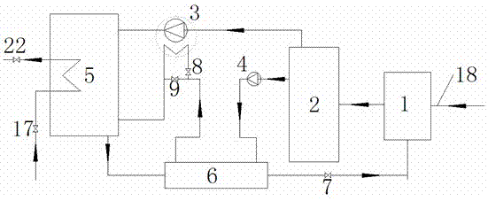
[0037] see figure 1 , the high-efficiency environmental protection heat pump is a single-stage heat pump; the single-stage heat pump includes an evaporator 1, a steam-water separator 2, an ammonia compressor 3, an ammonia water pump 4, an absorber 5 and a heat exchanger 6;
[0038] The ammonia water outlet of the evaporator 1 is connected with the A ammonia water separator 2 inlet, the A ammonia water separator 2 ammonia gas outlet is connected with the A ammonia gas compressor 3 inlet, and the A ammonia gas compressor 3 outlet is connected with the A absorber 5 ammonia gas inlet ;
[0039] The ammonia water outlet of the A ammonia water separator 2 is connected with the A ammonia water pump 4 inlet, the A ammonia water pump 4 outlet is connected with the first inlet of the A heat exchanger 6, and the first outlet of the A heat exchanger 6 is connected with the A regulating valve 8 and the A The inlet of bypass valve 9 is communicated;
[0040] The outlet of the A regulating v...
Embodiment 2
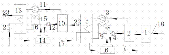
[0048] see figure 2 , the high-efficiency and environmentally friendly heat pump is a two-stage structure based on a single-stage heat pump, and the first-stage heat pump includes an evaporator 1, a steam-water separator 2, an ammonia compressor 3, an ammonia water pump 4, and an absorber 5 and A heat exchanger 6;
[0049] The ammonia water outlet of the evaporator 1 is connected with the A ammonia water separator 2 inlet, the A ammonia water separator 2 ammonia gas outlet is connected with the A ammonia gas compressor 3 inlet, and the A ammonia gas compressor 3 outlet is connected with the A absorber 5 ammonia gas inlet ;
[0050] The ammonia water outlet of the A ammonia water separator 2 is connected with the A ammonia water pump 4 inlet, the A ammonia water pump 4 outlet is connected with the first inlet of the A heat exchanger 6, and the first outlet of the A heat exchanger 6 is connected with the A regulating valve 8 and the A The inlet of bypass valve 9 is communicat...
Embodiment 3
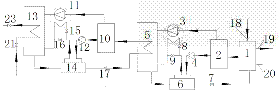
[0064] see image 3 , see figure 2 , the high-efficiency and environmentally friendly heat pump is a two-stage structure based on a single-stage heat pump, and the first-stage heat pump includes an evaporator 1, a steam-water separator 2, an ammonia compressor 3, an ammonia water pump 4, and an absorption Device 5 and A heat exchanger 6;
[0065] The ammonia water outlet of the evaporator 1 is connected with the A ammonia water separator 2 inlet, the A ammonia water separator 2 ammonia gas outlet is connected with the A ammonia gas compressor 3 inlet, and the A ammonia gas compressor 3 outlet is connected with the A absorber 5 ammonia gas inlet ;
[0066] The ammonia water outlet of the A ammonia water separator 2 is connected with the A ammonia water pump 4 inlet, the A ammonia water pump 4 outlet is connected with the first inlet of the A heat exchanger 6, and the first outlet of the A heat exchanger 6 is connected with the A regulating valve 8 and the A The inlet of byp...
PUM
 Abstract
Description
Claims
Application Information