Cladding light filtering structure and manufacturing method thereof

A cladding light and filtering technology, which is applied in the direction of the structure/shape of the active medium, can solve the problems of high local temperature, limited filtering capacity, and absolute increase, so as to achieve uniform temperature distribution, eliminate excessive heat concentration, and reduce The effect of temperature break point

Inactive Publication Date: 2013-08-28
SHANGHAI FEIBO LASER TECH CO LTD
View PDF5 Cites 29 Cited by
  • Summary
  • Abstract
  • Description
  • Claims
  • Application Information

AI Technical Summary

Problems solved by technology

Because the excess cladding light decays approximately exponentially in the filter layer, the above-mentioned coating layer absorbs a lot of heat in the first short period, resulting in excessive local temperature, which greatly limits its filtering ability
[0009] As the output power of fiber lasers or amplifiers continues to increase, the absolute amount of excess inner cladding light that needs to be filtered out is also increasing. Therefore, the centralized coating and filtering scheme of a single material has become one of the bottlenecks that affect the increase in the output power of fiber lasers or fiber amplifiers.

Method used


Image

  • Cladding light filtering structure and manufacturing method thereof
  • Cladding light filtering structure and manufacturing method thereof
  • Cladding light filtering structure and manufacturing method thereof

Examples


Embodiment 1

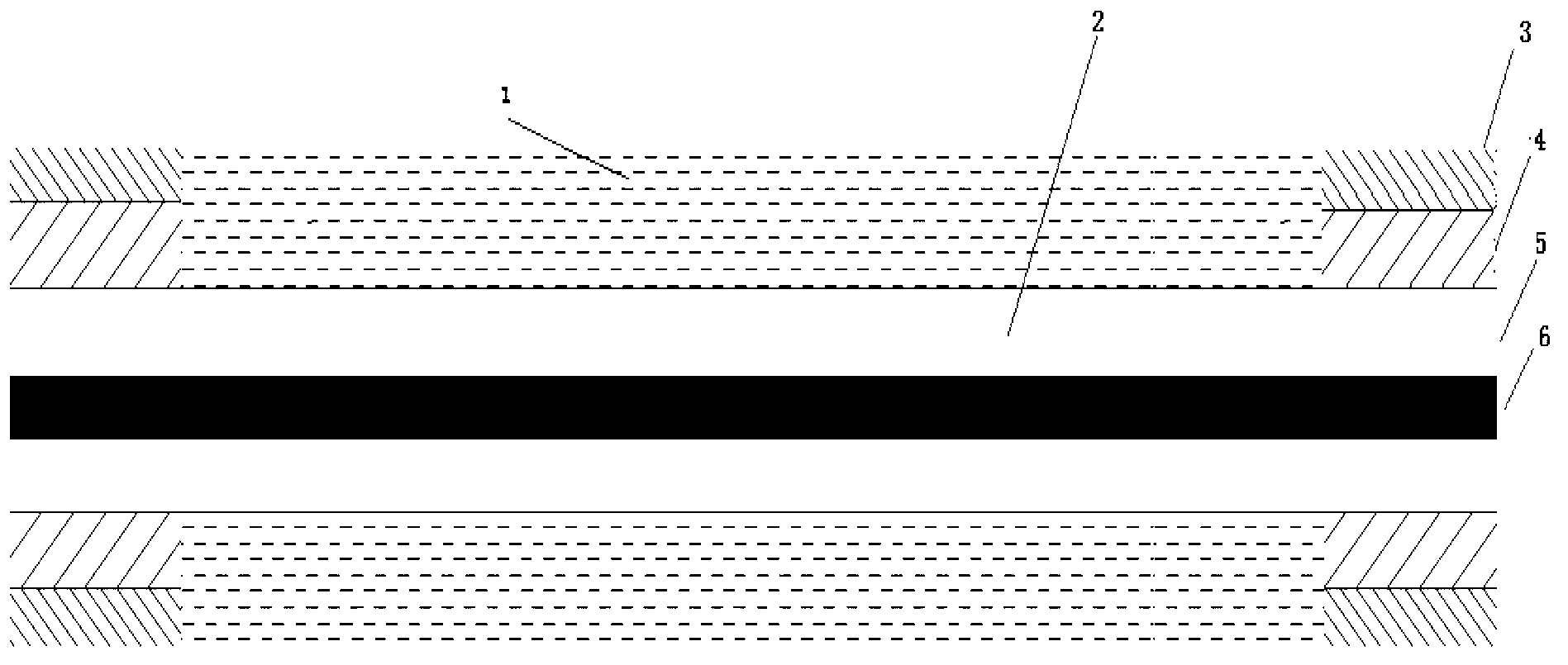
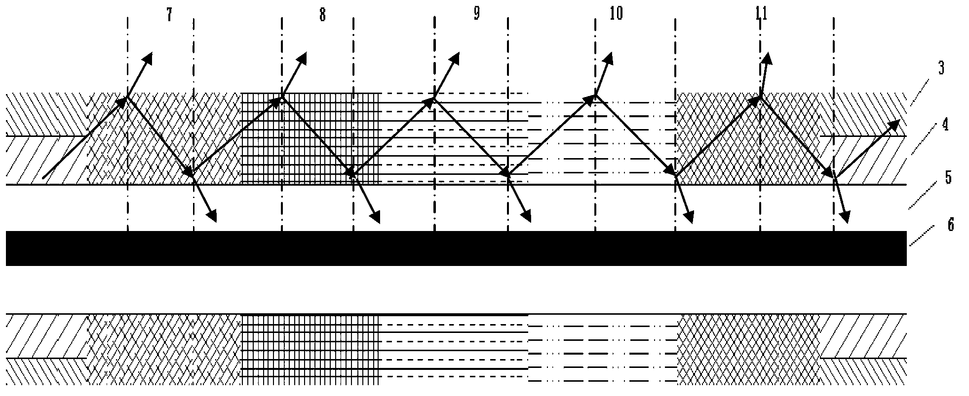
[0045] see first image 3 , image 3 It is a schematic diagram of filtering in which various filter materials are continuously coated in sections in Example 1 of the present invention. It can be seen from the figure that the cladding light filtering structure of this embodiment includes peeling off the protective layer 3, the outer cladding 4, and exposing a section of glass cladding. Layer 5 of the optical fiber 2 and the coating of the filter material 1 on the glass cladding 5, the refractive index of the filter material 1 is higher than the refractive index of the outer cladding 4 of the optical fiber 2, the The filter material 1 coating is coated on the coating segment with five different filter materials in sequence, the interval between each coating segment is equal to zero, and the refraction of the filter material of each coating segment The rate increases gradually from small to achieve relatively uniform filtered light of each coating segment.

[0046] A silica fib...

Embodiment 2

[0048] see first Figure 4 , Figure 4 It is a schematic diagram of the filtering of a single filter material segmented coating in Example 2 of the present invention. It can be seen from the figure that the cladding light filtering structure of this embodiment includes peeling off the protective layer 3 and the outer cladding 4, and exposing a section of the glass cladding The optical fiber 2 of 5 and the optical filter material 1 coating on the glass cladding 5, the refractive index of the optical filter material 1 is higher than the refractive index of the outer cladding 4 of the optical fiber 2, and the The coating of filter material 1 is a coating segment coated with the same filter material, and the interval between each coating segment is greater than zero, and the length of each coating segment gradually increases from short to long. The filtered light reaching each coating segment is relatively uniform.

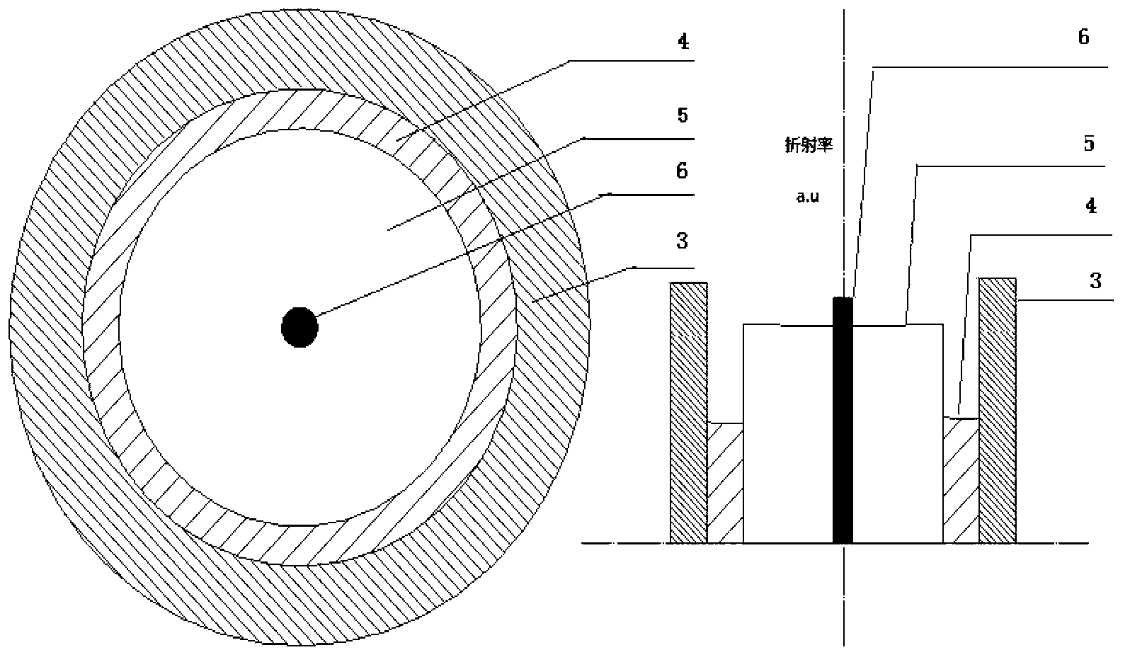
[0049] In this embodiment, a silica fiber with a core 6 diameter...


PUM


Abstract

The invention discloses a cladding light filtering structure for filtering out cladding light in a double-cladding or multi-cladding fiber laser system and a manufacturing method of the cladding light filtering structure. The cladding light filtering structure comprises an optical fiber and a filtering material coating layer, wherein a protective layer and an outer cladding layer of the optical fiber are removed, and a section of glass cladding layer is exposed. The refractive index of the filtering materials is higher than the refractive index of the outer cladding layer of the optical fiber, and the coating layer of the filtering materials is the filtering materials and is coated in a subsection mode. Due to the fact that refractive index, coating length and coating space of the filtering materials are matched, filtering quantity of all sections is roughly the same, highest temperature jump of an optical filter in a working state is reduced, reliability of the system is improved, and the more the subsections and the types of the materials are, the better the effect is.

Description

technical field [0001] The invention relates to a fiber laser or a fiber amplifier, in particular to a cladding light filtering structure for a fiber laser or a fiber amplifier and a preparation method thereof. technical background [0002] The output power of fiber lasers continues to increase, and the output power of a single unit of more than 10,000 watts has been achieved. Such a high output power is mainly due to the development of optical fiber and pump source technology. Usually, fiber lasers or fiber amplifiers with an output power exceeding 1 watt use double-clad active fibers as gain fibers. The so-called double-clad optical fiber generally consists of a core 6, a glass cladding 5, a low refractive index outer cladding 4, and an optional polymolecular polymer protective layer 3, such as figure 1 . The low refractive index outer cladding 4 is usually a multimolecular polymer with a refractive index around 1.36. The refractive index of the fiber core 6 is general...

Claims


Application Information

Patent Timeline
Patent Type & Authority Applications(China)
IPC IPC(8): H01S3/067
Inventor 李骁军侯晓亮彭彪
Owner SHANGHAI FEIBO LASER TECH CO LTD
Why Eureka
Try Eureka