Anti-reflux control device and photovoltaic energy storage connecting grid power generation method thereof

An anti-backflow controller and control device technology, applied in photovoltaic power generation, AC network load balancing, energy reserve and other directions, can solve the problems of low reliability and reduce the power generation of photovoltaic power plants, and achieve the effect of maximizing power generation efficiency

Inactive Publication Date: 2013-08-28
SHANGHAI INST OF SPACE POWER SOURCES
View PDF4 Cites 13 Cited by
  • Summary
  • Abstract
  • Description
  • Claims
  • Application Information

AI Technical Summary

Problems solved by technology

[0002] Due to the low reliability of new energy power generation systems such as photovoltaics and wind power, and the establishment of smart grids has not yet been completed, in order to ensure that the electricity generated by photovoltaic power generation systems is directly supplied to local loads instead of being fed to the grid, it is necessary to An anti-backflow control device is added to the grid power generation system to monitor the voltage and current on the grid side of the grid-connected point in real time. At present, the anti-backflow control device on the market is to connect a contactor in series at the node where the new energy is connected to the grid, and at the same time detect the voltage and current of the grid side. When a certain amount of current is sent into the grid, the contactor is disconnected to ensure that no power flows into the grid
This design ensures that energy will not flow into the grid, but on the other hand, the use of anti-backflow control devices reduces the power generation of photovoltaic power plants

Method used


Image

  • Anti-reflux control device and photovoltaic energy storage connecting grid power generation method thereof

Examples


Embodiment Construction

[0019] The specific embodiments of the present invention will be further described below with reference to the accompanying drawings.

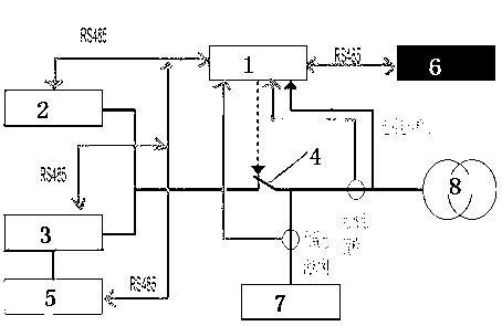
[0020] like figure 1 As shown, the anti-reverse flow control device provided by the present invention includes an anti-reverse flow controller 1, a photovoltaic inverter 2, a bidirectional inverter 3, an output contactor 4, an energy storage system 5, a monitoring computer 6, a local load unit 7 and a power grid. Unit 8; Photovoltaic inverter 2, bidirectional inverter 3, energy storage system 5, monitoring computer 6 are respectively connected with anti-backflow controller 1 through RS485 Ethernet; energy storage system 5 is connected with bidirectional inverter 3, energy storage The system 5 is preferably a battery assembly; the grid unit 8 is connected to the local load unit 7, and then connected to the photovoltaic inverter 2 and the bidirectional inverter 3 after passing through the output contactor 4; the anti-backflow controller 1 contro...


PUM


Abstract

The invention discloses an anti-reflux control device and a photovoltaic energy storage connecting grid power generation method thereof. The device comprises an anti-reflux controller, a photovoltaic inverter, a bidirectional inverter, an output contactor, an energy storage system, a monitoring computer, a local load unit and a power grid unit, wherein the photovoltaic inverter, the bidirectional inverter, the energy storage system and the monitoring computer are respectively connected with the anti-reflux controller through the RS485 Ethernet; the energy storage system is connected with the bidirectional inverter; the power grid unit is connected with the local load unit and then is respectively connected with the photovoltaic inverter and the bidirectional inverter after passing through the output contactor; and the output contactor is controlled to be closed and opened by the anti-reflux controller, and the anti-reflux control device also can be used for detecting the electric current of the local load unit, the electric current of the power grid unit and the voltage of the power grid unit. The invention also provides the photovoltaic energy storage connecting grid power generation method of the device, electric power sent out by a photovoltaic connecting grid power generation station can not flow backwards to the power grid, and simultaneously energy is fully utilized.

Description

technical field [0001] The invention relates to the technical field of grid-connected power generation, and in particular, to a backflow prevention control device and a method for photovoltaic energy storage and grid-connected power generation. Background technique [0002] Due to the low reliability of the current photovoltaic, wind power and other new energy power generation systems, and the smart grid has not yet been established, in order to ensure that the power generated by the photovoltaic power generation system is directly supplied to local loads and not fed to the power grid, it is necessary to An anti-backflow control device is added to the grid power generation system to monitor the voltage and current on the grid side of the grid connection point in real time. Currently, the anti-backflow control devices on the market are all connected in series with a contactor at the node where the new energy is connected to the grid, and at the same time detect the grid side. ...

Claims


Application Information

Patent Timeline
Patent Type & Authority Applications(China)
IPC IPC(8): H02J3/38H02J3/32
CPCY02E10/56Y02E70/30
Inventor 冯毅王谌张邦玲解晶莹
Owner SHANGHAI INST OF SPACE POWER SOURCES
Why Eureka
Try Eureka