A backup power supply control circuit

A technology of power supply control circuit and backup power supply, applied in the field of information, can solve the problems of many electronic components, low stability and reliability, complex circuit, etc., and achieve the effect of large distribution space, avoiding complex circuit, and simple circuit structure

Active Publication Date: 2016-05-25
浙江南峰电气有限公司
View PDF5 Cites 0 Cited by
  • Summary
  • Abstract
  • Description
  • Claims
  • Application Information

AI Technical Summary

Problems solved by technology

[0009] The technical problem to be solved by the present invention is that the existing backup power supply control circuit has many electronic components, the circuit is complicated, and the stability and reliability are not high, so as to provide a backup power supply control circuit with simple design, high stability and reliability

Method used


Image

  • A backup power supply control circuit
  • A backup power supply control circuit
  • A backup power supply control circuit

Examples


Embodiment 1

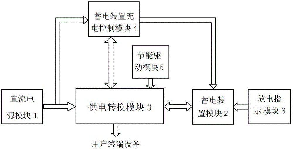
[0041] This embodiment provides a backup power supply control circuit, its structural block diagram is as follows figure 1 As shown, it includes a DC power supply module 1 , an electrical storage device 2 , a power supply conversion module 3 and a charging control module 4 for the electrical storage device.

[0042] The DC power supply module 1 includes an output terminal, and the DC power supply module 1 is used to provide DC power externally.

[0043] In this embodiment, the DC power supply module 1 includes an AC power supply and a rectifier, wherein the rectifier is used to rectify the AC power into a DC power, the rectifier includes an input terminal and an output terminal, and the input terminal of the rectifier is connected to the The output end of the AC power supply is connected, and the output end of the rectifier outputs direct current to the outside.

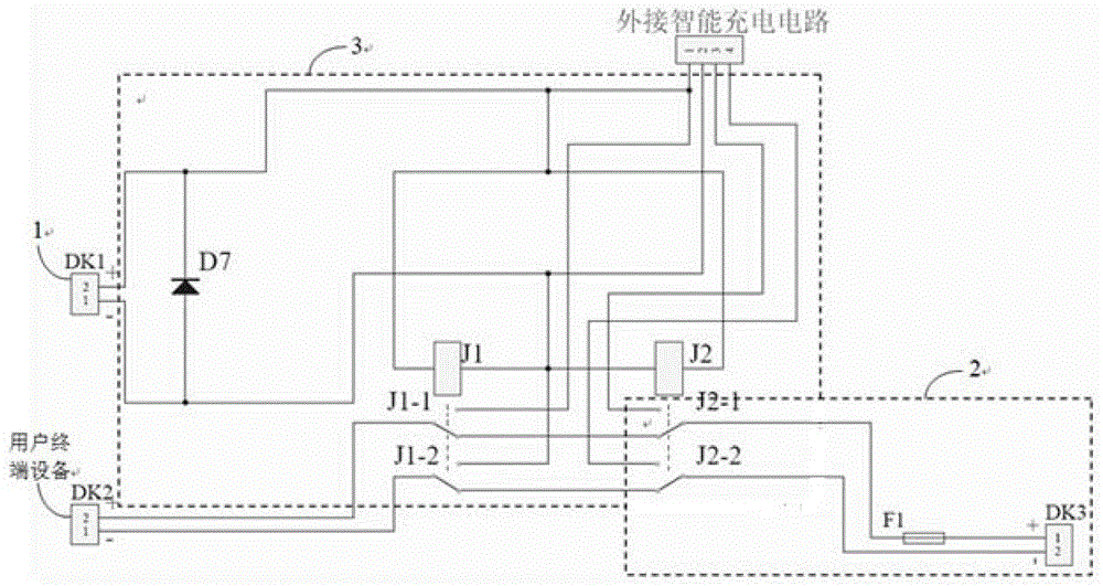
[0044] The power storage device 2 includes an input terminal and an output terminal, and the power storage device...

Embodiment 2

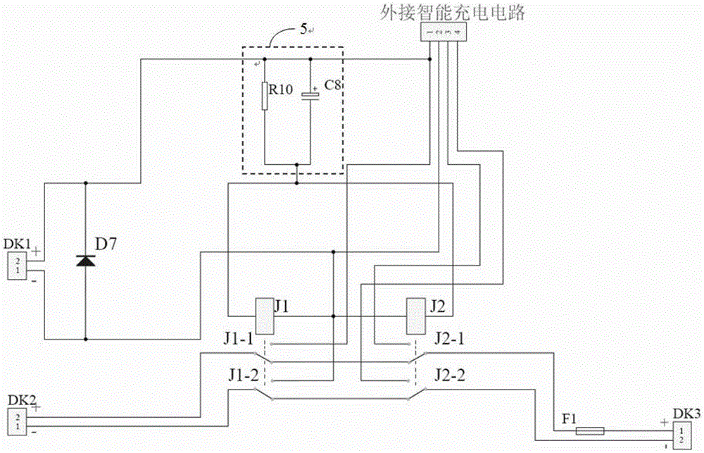
[0067] On the basis of Embodiment 1, the backup power supply control circuit further includes an energy-saving drive module 5 for driving the power conversion module 3 .

[0068] In this example, if image 3 As shown, the energy-saving drive module 5 includes a resistor R10 and a polar capacitor C8; one end of the resistor R10 and the positive pole of the polar capacitor C8 are connected together as the input terminal of the energy-saving drive module 5 and connected to the DC The output end of the power supply module 1 is positive, the other end of the resistor R10 and the negative end of the polarity capacitor C8 are connected together as the output end of the energy-saving drive module 5 and connected to the first input end of the power supply conversion module 3 . The energy-saving drive module 5 utilizes the reverse electromotive force when the polar capacitor C8 is discharged to enhance the energy-saving drive current of the relay coil, accelerate the action speed of th...

Embodiment 3

[0070] On the basis of the first and second embodiments above, the backup power supply control circuit further includes a discharge indication module 6 for indicating whether the power storage device 2 is in a discharge state.

[0071] In this example, if Figure 4 As shown, the discharge indicating module 6 includes a resistor R11 and a light-emitting diode D8; the anode of the light-emitting diode D8 is connected to one end of the resistor R11, and the other end of the resistor R11 is connected to the output terminal of the power storage device 2. The negative pole of the light-emitting diode D8 is connected to the negative pole of the output terminal of the power storage device 2 . When the light-emitting diode D8 is on, it indicates that the power storage device 2 supplies power to the user terminal equipment; when the light-emitting diode D8 is off, it indicates that the power storage device 2 does not supply power to the user terminal equipment.


PUM


Abstract

The invention provides a back-up source power supply control circuit which comprises a direct current power module, an electrical storage device, a power supply conversion module and an electrical storage device charging control module. When the direct current power module provides a direct current to subscriber terminal equipment, a voltage of the electrical storage device is detected by the electrical storage device charging control module, the electrical device charging control module controls the electrical storage device to stop being charged when the voltage of the electrical storage device is higher than or equal to an larger threshold value of a preset voltage, the electrical storage device charging control module outputs the direct current to the electrical storage device when the voltage of the electrical storage device is lower than a smaller threshold value of the preset voltage, the power supply conversion module controls the electrical storage device to provide electric power to the subscriber terminal equipment when the direct current power supply module does not provide the direct current outward, and therefore the subscriber terminal equipment keeps normal operation and protects hardware and software from damage. The back-up source power supply control circuit is simple in structure and low in cost. On the basis of existing devices of public users, the back-up source power supply control circuit which is relatively high in stability and reliability is developed.

Description

technical field [0001] The invention relates to a backup power supply device, in particular to a backup power supply control circuit, which belongs to the field of information technology. Background technique [0002] The backup power supply is an automatic driving quasi-power supply that effectively prevents the drive circuit of the user terminal equipment from having normal voltage, and is used to provide power for the user terminal equipment to work normally. [0003] The backup power supply can realize zero-time switching of the power supply of various power supply devices, the length of its own power supply time is optional, and has the characteristics of voltage stabilization, frequency stabilization, and purification. It is an important device to ensure the stability and continuity of power supply. The backup power supply solves the problems of power failure, undervoltage, overvoltage and other problems of the existing electric power, and makes the operation of power ...

Claims


Application Information

Patent Timeline
Patent Type & Authority Patents(China)
IPC IPC(8): H02J9/06
CPCY02B70/30Y04S20/20
Inventor 周庆南
Owner 浙江南峰电气有限公司
Why Eureka
Try Eureka