Powder feeding dust removal device

A technology of dust removal device and powder, which is applied in the direction of cyclone device, etc., can solve the problems of air pollution, high labor intensity, high device cost, etc., and achieve the effects of reducing labor intensity, scientific and reasonable operation, and reasonable structural design

Active Publication Date: 2015-08-05
大庆市考维尔自动化设备制造有限公司
View PDF5 Cites 1 Cited by
  • Summary
  • Abstract
  • Description
  • Claims
  • Application Information

AI Technical Summary

Problems solved by technology

However, its structural design is unreasonable and its technical content is not high, which is reflected in the dust removal process, which is mainly realized by the three-stage dust removal method of the first-stage cyclone dust collector, the second-stage cyclone dust collector and the third-stage cyclone dust collector. High, and in the process of feed dust removal, the dust removal effect will vary with the feed amount. Although most of them can be separated, there will still be some impurities with smaller particles that will be discharged along the outlet of the fan. , the dust removal effect is not good, forming air pollution
It affects and destroys the surrounding environment, and the cyclone dust collector cannot be effectively controlled. The only thing that can be controlled is to control the source of the feed, but it increases a lot of labor intensity for the operator, and the result is not good for dust removal. The efficiency and quality achieved in the process are not ideal

Method used


Image

  • Powder feeding dust removal device
  • Powder feeding dust removal device
  • Powder feeding dust removal device

Examples


Embodiment 1

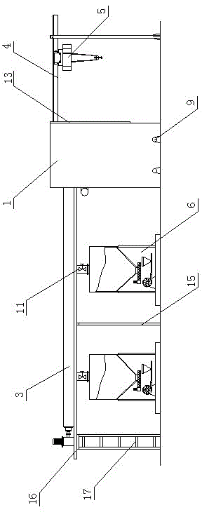
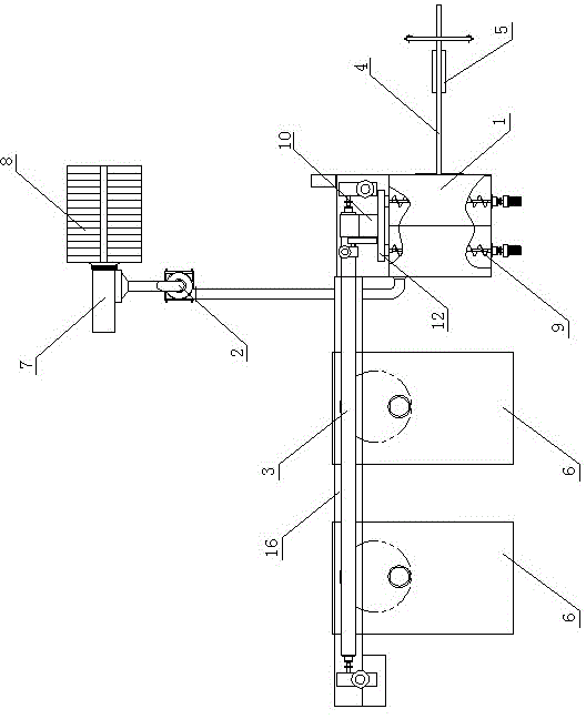
[0017] The powder feeding and dedusting device of the present invention is composed of a powder chamber 1, a cyclone separator 2 and a powder conveying distributor 3. A bin door 13 is provided above one end of the powder chamber 1. The upper part of the powder chamber 1, the bin One end of the door 13 is horizontally provided with a bracket-type guide rail 4 leading to the inside of the powder chamber 1, a traction crane 5 is installed on the bracket-type guide rail 4, and the other end of the powder chamber 1 opposite to the bracket-type guide rail 4 is horizontally provided with a powder chamber. Material conveying distributor 3, more than one group of dispersion tanks 6 are arranged below the powder conveying distributor 3 to communicate with their pipelines; one side pipeline of the powder chamber 1 is connected to the cyclone separator 2, and the outlet of the cyclone separator 2 is connected to the fan 7 is connected, the outlet of the fan 7 is connected to the fine powde...

Embodiment 2

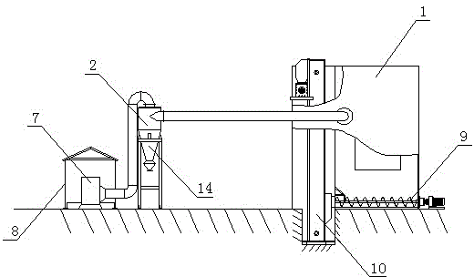
[0019] The powder feeding and dedusting device of the present invention is composed of a powder chamber 1, a cyclone separator 2 and a powder conveying distributor 3. A bin door 13 is provided above one end of the powder chamber 1. The upper part of the powder chamber 1, the bin One end of the door 13 is horizontally provided with a bracket-type guide rail 4 leading to the inside of the powder chamber 1, on which a traction crane 5 is installed, and the other end of the powder chamber 1 opposite to the bracket-type guide rail 4 is horizontally provided with a powder chamber. The material conveying distributor 3 is provided below the powder conveying distributor 3 with more than one group of dispersion tanks 6 communicating with its pipeline, and a control valve 11 is arranged on the connected pipeline. One side of the pipeline of the powder chamber 1 is connected to the cyclone separator 2, and the dust-reducing cylinder 14 of the cyclone separator 2 is a spiral inverted cone. ...


PUM


Abstract

The invention discloses a feeding and dedusting device of powder, which belongs to a device for preventing dirt or snoot from escaping. The feeding and dedusting device of powder is composed of a powder chamber, a cyclone separator, and a powder transportation distributer, wherein a guide rail is horizontally arranged at one side of the upper part of the powder chamber; a tractor crane is arranged on the guide rail; the powder transportation distributer is horizontally arranged on the powder chamber at the opposite side of the guide rail; more than one group of dispersing tanks are arranged below the powder transportation distributer and communicated with a pipeline of the powder transportation distributer; the pipeline of the powder chamber is connected with the cyclone separator; the other end of the cyclone separator is communicated with a fan; and more than one group of spiral conveyers and more than one group of powder elevators are longitudinally arranged are transversely arranged at the lower part inside the powder chamber. The feeding and dedusting device of powder disclosed by the invention is reasonable in structural design, and good in dust removal effect; the traditional three-stage dust removal is changed into one-stage dust removal; the flow is simplified; the construction cost of the device is reduced; and the entire device is scientific and reasonable in sequential operations of each link from front to back, so that the dust removal can achieve the maximal efficiency and benefit.

Description

technical field [0001] The invention belongs to a device for preventing dirt or smoke from escaping from the generator, and in particular relates to a powder feeding and dedusting device. Background technique [0002] In the field of tertiary oil recovery in the late stage of oilfield exploitation, polymer flooding technology has been applied on a large scale and has become an ideal flooding method to increase and stabilize oilfield production. Although it can greatly improve oil recovery, its investment is large and the cost However, in the current injection stations of various configuration stations in oil fields, when using mechanical equipment to dissolve, mix and stir powder materials, they usually use the open feeding method of overhead cranes, which cannot guarantee the timeliness and continuity of the main materials. It will produce a lot of dust and serious pollution. The staff must be in direct contact with the dust, which seriously affects the health and is not h...

Claims


Application Information

Patent Timeline
Patent Type & Authority Patents(China)
IPC IPC(8): B04C9/00
Inventor 高城
Owner 大庆市考维尔自动化设备制造有限公司
Why Eureka
Try Eureka