

High-speed mill roll shaft
A high-speed rolling mill, roll shaft technology, applied in the direction of metal rolling stand, metal rolling mill stand, metal rolling, etc.
Active Publication Date: 2013-09-04
ZHEJIANG PENGCHENG TECH
View PDF4 Cites 0 Cited by
- Summary
- Abstract
- Description
- Claims
- Application Information
AI Technical Summary
Problems solved by technology
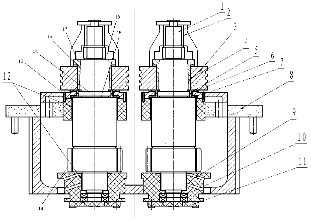
[0004] The technical problem to be solved by the present invention is to provide a high-speed rolling mill roll shaft, solve the deformation of the roll shaft in the deformation rolling process, and control the influence of the deformation on the roll shaft and bearings, and at the same time, improve the strength and durability of the roll shaft. Abrasive
Method used
View moreImage
Smart ImageViewing Examples

Examples
specific example 1
[0024] Specific example 1, C0.10; Si≤0.2; Mn0.40; S≤0.035; P≤0.035; Cr≤1.8; Ni2.4; Mo0.3; W0.1; B0.00025; Cu1.3.
specific example 2
[0025] Specific example 2, C0.15; Si≤0.2; Mn0.60; S≤0.035; P≤0.035; Cr≤2.1; Ni2.8; Mo0.4; W0.15; B0.00035; Cu1.8.
specific example 3
[0026] Specific example 3, C0.10; Si≤0.2; Mn0.40-0.60; S≤0.035; P≤0.035; Cr≤2.0; Ni2.6; Mo0.4; W0.1; B0.0002;
Login to View More PUM
| Property | Measurement | Unit |
|---|---|---|
| Thickness | aaaaa | aaaaa |
Abstract
The invention discloses a high-speed mill roll shaft. Oil film bearings are installed at the front end and the rear end of a roll shaft body. A taper transition structure is designed at the matched position of the front end of the roll shaft body and the oil film bearing. Roll shaft body alloy components of the roll shaft comprise, by mass, 0.10% to 0.15% of C, less than or equal to 2.15% of Cr, 0.40% to 0.605% of Mn, 0.1% to 0.15% of W, 0.00025% to 0.00035% of B, and 1.3% to 1.8% of Cu. According to the high-speed mill roll shaft, influences of deformation and deformation control of the roll shaft body in a deformation rolling process on the roll shaft body and the bearings are removed, and the phenomena of shaft burning and bearing burning can not be caused in a high-speed wire rod rolling process. In addition, the high-speed mill roll shaft is low in economic cost, and meanwhile has high toughness and abrasive resistance.
Description
technical field [0001] The invention relates to a roll shaft for a high-speed rolling mill. Background technique [0002] Due to the large radial pressure during the high-speed wire rolling process, the shaft is always in a slightly deformed state during the rolling process. The special oil film bearings for high-speed wire rolling are used on the roll shaft, especially for low-position rolling. When the roller shaft is subjected to a large torsion force, the roller shaft deforms greatly, and the oil film bearing and the roller shaft are supported by an oil film. When the roller shaft deforms greatly during use, the oil film between the roller shaft and the oil film bearing is likely to be unstable. As a result, the oil film is broken, and the roller box is burned after the roller shaft and the eccentric bushing are stuck, which seriously affects the normal production. [0003] In addition, the strength and wear resistance of the roller shaft alloys used in the high-speed w...
Claims
Login to View More Application Information
Patent Timeline
 IPC IPC(8): B21B31/00
Inventor王勇伟
OwnerZHEJIANG PENGCHENG TECH