
Steel template system used for subway foundation pit supporting beam

A technology of steel formwork and support beams, which is applied in infrastructure engineering, water conservancy projects, artificial islands, etc., can solve problems such as failure to reach support beams, insufficient support force, easy deformation, etc., to prevent structural deformation, improve quality, Non-deformable effect

Active Publication Date: 2013-09-04
GUANGZHOU JISHI CONSTR GRP +1
View PDF7 Cites 6 Cited by
  • Summary
  • Abstract
  • Description
  • Claims
  • Application Information

AI Technical Summary

Problems solved by technology

The steel formwork system formed by splicing small steel formworks has poor integrity and is easy to run out and deform
Moreover, the parallel tie rods are used to support each other between the steel formworks arranged side by side, which requires the plastic pipes of the tie rods to be pre-embedded in the reinforced concrete. The length span is relatively large, the formwork itself is prone to distortion and deformation, the strength of the formwork is insufficient, and the support force is not enough. After pouring concrete, the formwork is also prone to deformation under greater pressure, which will cause lateral torsional deformation of the support beam. If the deformation is too large, it will not reach the support beam. Requirements, even exposed steel bars, which is unacceptable in construction, lateral torsional deformation will also lead to cracks at the joint position of the formwork, resulting in grout leakage
Moreover, the existing support beam steel formwork has many splicing times, and the installation and disassembly are time-consuming and labor-intensive

Method used


Image

  • Steel template system used for subway foundation pit supporting beam
  • Steel template system used for subway foundation pit supporting beam
  • Steel template system used for subway foundation pit supporting beam

Examples


Embodiment Construction

[0020] The specific embodiments of the present invention will be further described below in conjunction with the accompanying drawings.

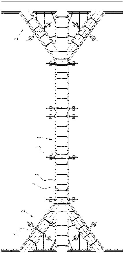
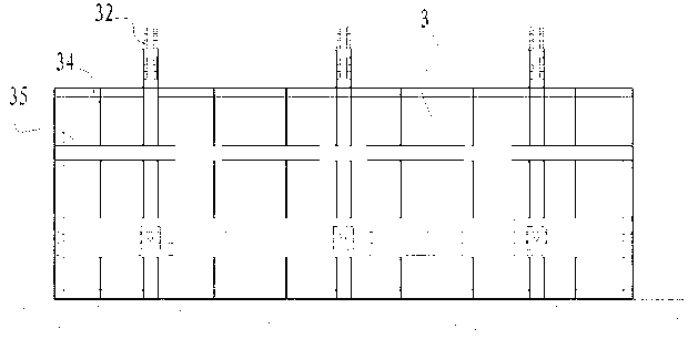
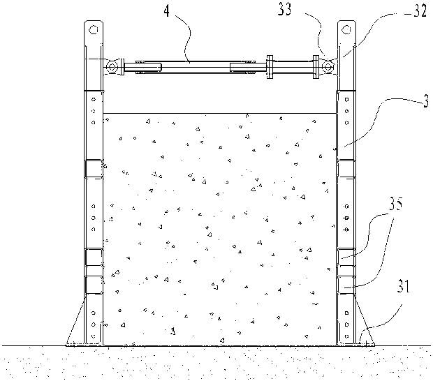
[0021] figure 1 It is a general structure diagram of an embodiment of the steel formwork system used for supporting beams in subway foundation pits according to the present invention. The embodiment of the present invention includes a main beam formwork 1 located in the middle and diagonally braced beam formworks 2 located at both ends. Further, the inclined The supporting beam formwork forms the shape of the head and tail of the Chinese character "米", that is, the steel formwork system of the present invention presents the shape of the Chinese character "米" without the middle horizontal line. Both the main girder formwork and the braced beam formwork are made of steel formwork 3 arranged in parallel and opposed to each other. The bottom of the steel formwork 3 is provided with a foot support 31 that can be locked with the ground. The foot s...


PUM


Abstract

The invention discloses a steel template system used for a subway foundation pit supporting beam. The steel template system comprises a main beam template and diagonal bracing beam templates, wherein the main beam template is located in the middle, the diagonal bracing beam templates are located at the two ends, the main beam template and the diagonal bracing beam templates are formed by steel templates in a parallel and opposite mode, the bottoms of the steel templates are provided with foot braces which can be locked with the ground, the oppositely-arranged steel templates are connected and supported through jack screws at the tops of the steel templates, the outer side of each steel template is provided with an outer supporting framework which can support and abut against the steel templates, each outer supporting framework comprises a portal frame and supporting rod assemblies, each portal frame is provided with a portal frame cross beam and stand columns, the supporting rod assemblies are installed on the stand columns and used for supporting the steel templates, each supporting rod assembly comprises a supporting board used for abutting against the steel templates, and a supporting rod used for adjusting the supporting board to move back and forth, each supporting board is connected to the end portion of one supporting rod, and the supporting rods are screws and penetrate through the stand columns and are in threaded connection with the stand columns. By the adoption of the technical scheme, the steel template system is good in integrality, the templates do not deform easily, fixation is firm, the supporting beam is prevented from producing structural deformation when concreted is poured, and assembly and disassembly are rapid and convenient.

Description

technical field [0001] The invention relates to a steel formwork for supporting beams, in particular to a steel formwork system for supporting beams in subway foundation pits. Background technique [0002] In the construction of supporting beams in subway foundation pits, wooden formwork is traditionally used, which has a cumbersome process, poor formwork quality, and easy formwork runaway. In addition, small steel formwork is used, and the whole support beam formwork is formed by connecting the small steel formworks in sequence. Even in the height direction, it needs to be spliced ​​by multiple small steel formworks. The steel formwork system formed by splicing small steel formworks has poor integrity and is prone to formwork deformation. Moreover, the parallel tie rods are used to support each other between the steel formworks arranged side by side, which requires the plastic pipes of the tie rods to be pre-embedded in the reinforced concrete. The length span is relative...

Claims


Application Information

Patent Timeline
Patent Type & Authority Applications(China)
IPC IPC(8): E02D29/045E02D17/02
Inventor 何炳泉邱师亮黎文龙邱建涛秦建新黄平宇麦伟简炳新李俊沅王志蒋明曦刘斯琴唐伟才
Owner GUANGZHOU JISHI CONSTR GRP
Learn More