Geotechnical engineering on-site detection method and device

An on-site detection and geotechnical engineering technology, which is applied in infrastructure engineering, infrastructure testing, construction, etc., can solve problems such as low detection efficiency, human theft, and system fragility, so as to facilitate the concealment of sensors and prevent omission of measurement points , to avoid the effect of missing measurement points

Active Publication Date: 2013-09-04
武汉中岩科技股份有限公司
View PDF5 Cites 3 Cited by
  • Summary
  • Abstract
  • Description
  • Claims
  • Application Information

AI Technical Summary

Problems solved by technology

[0002] A large number of detection and monitoring projects in the field of geotechnical engineering, such as foundation settlement monitoring, slope safety monitoring, tunnel deformation monitoring, etc., often last for several years, and the detection and monitoring environment is also very complex and harsh, and even faces the problem of man-made damage
[0003] The existing technology is mainly manual detection. The problem is that manual detection has low efficiency and high failure rate. Taking the vibrating wire sensor and strain sensor widely used in detection and monitoring as an example, the current detection and monitoring methods are mainly manual operation. , During detection, the staff carries the reader to a measuring point, temporarily connects the reader to the sensor buried at the measuring point, and after reading the detection value, disconnects the reader from the sensor, and then proceeds to the next measuring point detection
There are often hundreds of (or even more) measuring points on a construction site. This detection method is very inefficient. Sometimes, in order to prevent intentional or unintentional damage, the connection lines of the sensors must be hidden, and the connection lines must be hidden repeatedly. And taking out the connection leads to lower detection efficiency, and repeatedly connecting and disconnecting the sensor to the reader can easily

Method used


Image

  • Geotechnical engineering on-site detection method and device
  • Geotechnical engineering on-site detection method and device
  • Geotechnical engineering on-site detection method and device

Examples


Embodiment 1

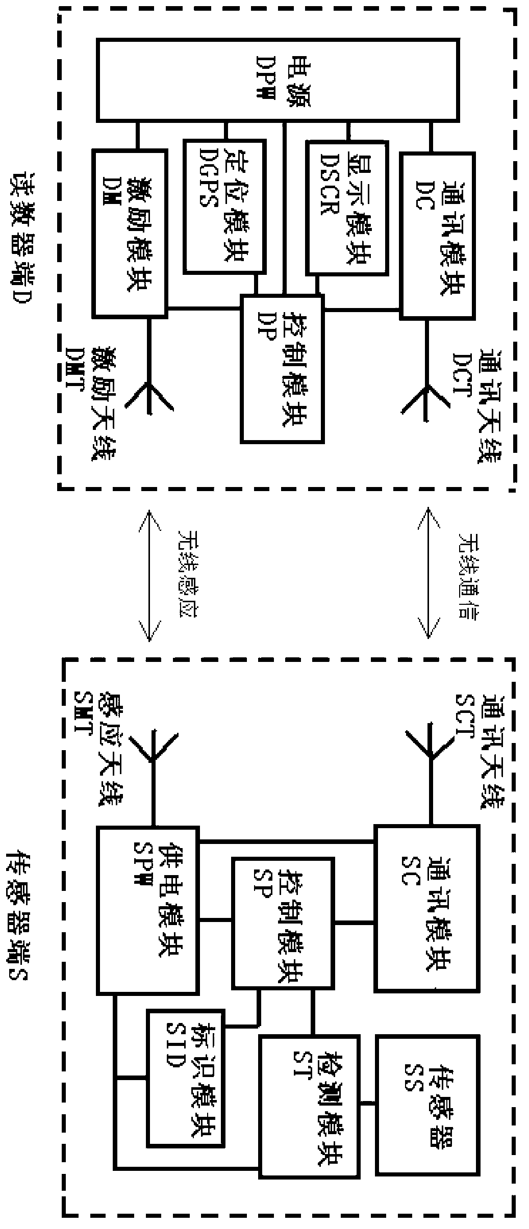
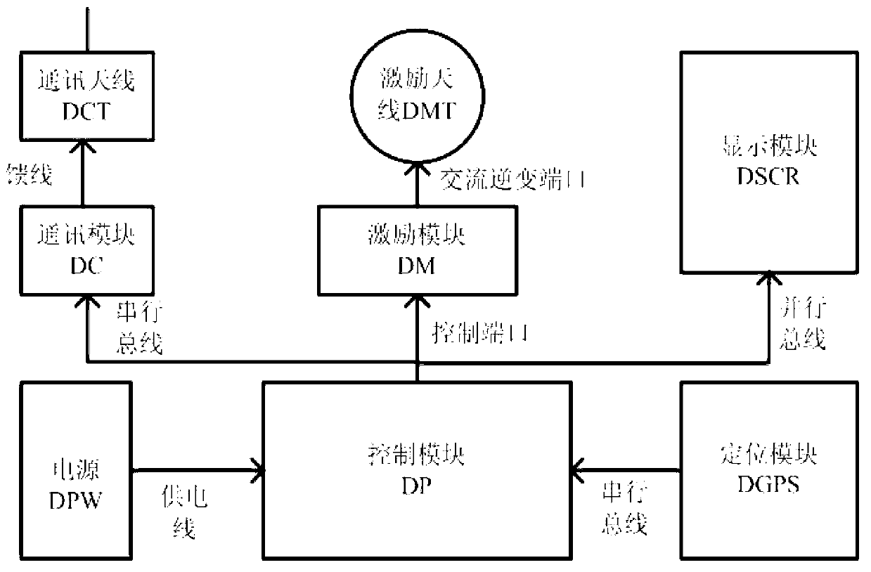
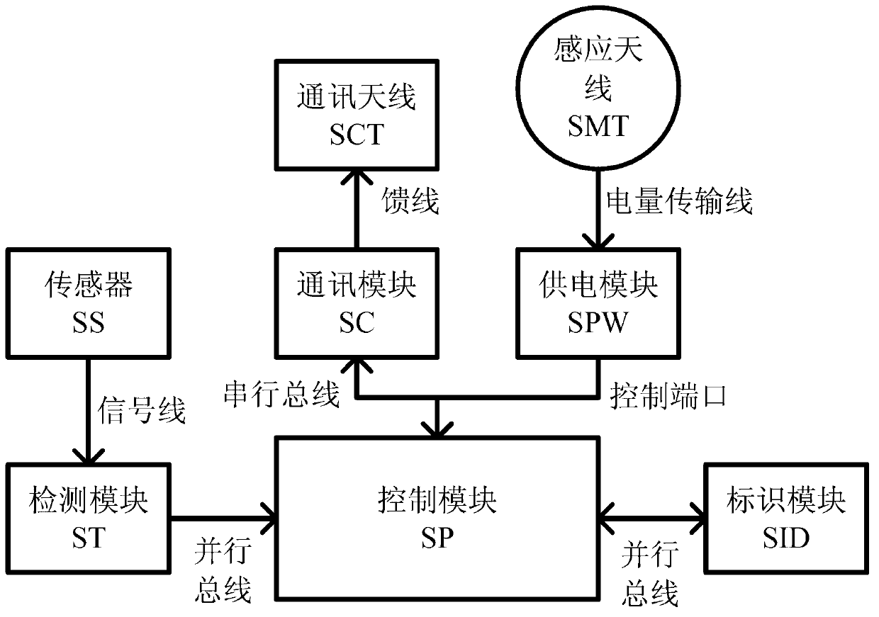
[0075] A geotechnical engineering site detection device ,This is a technical solution based on the sensor SS of the sensor terminal S as a strain gauge, the communication module DC of the reader terminal D and the communication module SC of the sensor terminal S based on 2.4G wireless transmission, and the supply mode of the sensor terminal S is based on the principle of resonance Directly rectified power supply. The structural block diagram of the reader terminal D is shown in Figure 2 (a), the circuit schematic diagram of the reader terminal D is shown in Figure 2 (b), the structural block diagram of the sensor terminal S is shown in Figure 3 (a), and the circuit schematic diagram of the sensor terminal S is shown in Fig. 3 (b1), the detection status process of the terminal D of the reader is shown in Figure 4 .

[0076] The device includes a reader terminal D and a sensor terminal S. The reader terminal D includes a power supply DPW, a control module DP, a display module...

Embodiment 2

[0124] A geotechnical engineering site detection device, which is an example of the sensor terminal S, is based on the sensor SS of the sensor terminal S as a vibrating wire displacement meter, and the communication module SC of the sensor terminal S is based on the technical scheme of 433M wireless transmission. The supply mode of S is to use a capacitive charge pump to realize power supply. The circuit schematic diagram of the sensor terminal S is shown in Figure 3 (b2), and the working process of the sensor terminal S is shown in Figure 5 (b).

[0125] The advantage of the charge pump technology is that it can accumulate charges in a relatively weak alternating electromagnetic field, so that the exciting antenna DMT at the reader end D can be farther away from the sensing antenna SMT at the sensor end S, for example, within 3 meters , to realize the power supply to the sensor terminal S. In a weak alternating electromagnetic field, the induced electromotive force induced b...


PUM


Abstract

The invention discloses a geotechnical engineering on-site detection method and device. The geotechnical engineering on-site detection device comprises a numerical reader end D and a sensor end S. The numerical reader end D is formed by a control module DP, a positioning module DGPS, a motivating module DM, a motivating antenna DMT, a communication module DC, a communication antenna DCT and a battery DPW. The sensor end S is formed by an induction antenna SMT, a power supply module SPW, a control module SP, an identification module SID, a detection module ST, a sensor SS, a communication module SC and a communication antenna SCT. The numerical reader end D adopts a wireless power supply mode to achieve power supply to the sensor end S, the sensor end S completes detection and sends detection data and sensing identification information to the numerical reader end D by means of a wireless communication mode, and the numerical reader end D records position information and stores the position information, the identification information and the detection data. The geotechnical engineering on-site detection device is high in detection efficiency, low in failure rate, capable of eliminating record errors, and long in service life.

Description

technical field [0001] The invention belongs to the field of geotechnical engineering detection and monitoring, and in particular relates to a geotechnical engineering on-site detection method, and also relates to a geotechnical engineering on-site detection device. Background technique [0002] A large number of detection and monitoring projects in the field of geotechnical engineering, such as foundation settlement monitoring, slope safety monitoring, and tunnel deformation monitoring, often last for several years, and the detection and monitoring environment is also very complicated and harsh, and even faces the problem of man-made damage. [0003] The existing technology is mainly manual detection. The problem is that manual detection has low efficiency and high failure rate. Taking the vibrating wire sensor and strain sensor widely used in detection and monitoring as an example, the current detection and monitoring methods are mainly manual operation. , During detection...

Claims


Application Information

Patent Timeline
IPC IPC(8): E02D33/00
Inventor 张杰胡纯军张喻王承成
Owner 武汉中岩科技股份有限公司
Why Eureka
Try Eureka