Supercharge Your Innovation With Domain-Expert AI Agents!

Oil-gas separator

A technology of oil-gas separator and separation tank, which is applied in the direction of machines/engines, engine components, mechanical equipment, etc. It can solve the problems of poor oil drop separation effect and increased volume of oil-gas separator for separation effect, and achieve reduced oil content and small volume Effect

Inactive Publication Date: 2013-09-04
SUZHOU CUIZHI NEW TECH DEV
View PDF1 Cites 4 Cited by
  • Summary
  • Abstract
  • Description
  • Claims
  • Application Information

AI Technical Summary

Problems solved by technology

[0005] In order to solve the disadvantages that the existing oil-gas separator has a poor separation effect on oil droplets of different particle sizes, and a small increase in the separation effect leads to a significant increase in the volume of the oil-gas separator, the present invention provides an oil-gas separator, which not only adopts a double oil-gas separation method, but also The two oil and gas separation devices are nested structures to further reduce the volume of the oil and gas separator

Method used


Image

  • Oil-gas separator
  • Oil-gas separator

Examples


Embodiment Construction

[0016] Describe an embodiment below in conjunction with accompanying drawing, the present invention is further described.

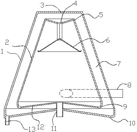
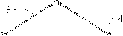
[0017] In the figure, a collision separation tank 2 is nested in the cyclone separation tank 1, and there is a gap between the cyclone separation tank 1 and the collision separation tank 2. The shape is frustum-shaped and the diameter of the bottom is larger than that of the top. The outline of the collision separation tank 2 is the same as that of the inner chamber 7 of the cyclone separation tank 1, and the diameter of the bottom is larger than that of the top. The bottom 10 of the cyclone separation tank is a conical surface, and the middle height is higher than the edge. An air inlet 8 is provided on the side of the bottom 10 of the cyclone separation tank, and the air inlet 8 communicates with the inner cavity 7 of the cyclone separation tank 1 . An air inlet 4 is arranged on the top surface of the collision separation tank, a conical oil separ...


PUM


Abstract

The invention discloses an oil-gas separator which comprises an engine oil separating tank, a gas inlet pipe, a gas exhaust pipe, and an engine oil discharging hole. A gas inlet is formed in one side of the lower portion of the engine oil separating tank. A cyclone separating tank is arranged outside the engine oil separating tank. The engine oil discharging hole is formed in the bottom of the cyclone separating tank. A collision separating tank is embedded in the cyclone separating tank in a sleeved mode. A gas inlet is formed in the upper portion of the collision separating tank. An oil separating cap is arranged at the gas inlet of the collision separating tank. An engine oil leakage hole is formed at the bottom of the collision separating tank. An exhaust pipe is arranged in the center of the bottom of the collision separating tank and is communicated with the outside. The oil-gas separator is small in size and further reduces the engine oil content of gas carry-over through double oil-gas separating modes.

Description

technical field [0001] The invention relates to an oil-gas separator, in particular to a small-volume oil-gas separator capable of dual oil separation by cyclone and collision. Background technique [0002] As we all know, in the engine of a car, when the engine is working, the blow-by gas containing a large amount of unburned hydrocarbons will blow into the crankcase from the gap between the piston and the cylinder. If the blow-by gas is released into the atmosphere, it will cause air pollution. In order to reduce the pollution of the atmosphere, the technical measure adopted is to return this blow-by gas to the suction system and let it burn again by means of so-called positive crankcase ventilation. Blow-by gas contains a large amount of oil mist formed by micronizing lubricating oil such as engine oil. If the blow-by gas containing oil mist is directly returned to the suction system, the inside of the suction system pipe will be polluted by the oil. Therefore, the tech...

Claims


Application Information

Patent Timeline
Patent Type & Authority Applications(China)
IPC IPC(8): F01M13/04
Inventor 孟繁茂
Owner SUZHOU CUIZHI NEW TECH DEV
Features
  • R&D
  • Intellectual Property
  • Life Sciences
  • Materials
  • Tech Scout
  • Unparalleled Data Quality
  • Higher Quality Content
  • 60% Fewer Hallucinations
Learn More