Constant volume combustion device for observing mutual effect of flame and pressure wave

A technology of constant volume combustion and pressure wave, which is applied in the direction of internal combustion engine testing, etc., can solve the problems of insufficient optimization of the inner cavity structure of constant volume incendiary bombs, interference with flame propagation, instability of flame combustion pressure waves and wall reflection waves, etc. The effect of maintaining or forming, ensuring the safety of the test, and not easy to leak

Inactive Publication Date: 2013-09-04
TIANJIN UNIV
View PDF5 Cites 32 Cited by
  • Summary
  • Abstract
  • Description
  • Claims
  • Application Information

AI Technical Summary

Problems solved by technology

[0005] What the present invention aims to solve is that the inner cavity structure of the existing constant-volume incendiary bombs is not optimized enough, which leads to the instability of the flame combustion pressure wave and its wall reflection wave, thereby interfering with the technology of effectively observing the flame combustion pressure wave and its wall reflection wave affecting flame propagation and spontaneous combustion The problem is to provide a constant volume combustion device for observing the interaction between the flame and the pressure wave, reduce the influence of the installation of the optical observation window on the combustion projectile on the regularity of the inner cavity, improve the smoothness of the inner cavity, and improve the internal flow. Field and wall pressure wave reflection effect; at the same time, change the force mode of the glass in the traditional optical observation window, reduce the thickness of the glass, and improve the observation and shooting effect of the experiment

Method used


Image

  • Constant volume combustion device for observing mutual effect of flame and pressure wave
  • Constant volume combustion device for observing mutual effect of flame and pressure wave
  • Constant volume combustion device for observing mutual effect of flame and pressure wave

Examples


Embodiment Construction

[0026] The present invention will be described in further detail below through specific examples. The following examples can enable those skilled in the art to understand the present invention more comprehensively, but do not limit the present invention in any way.

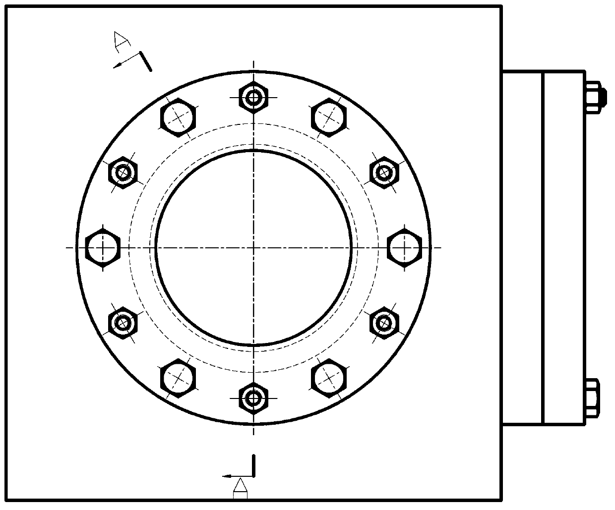
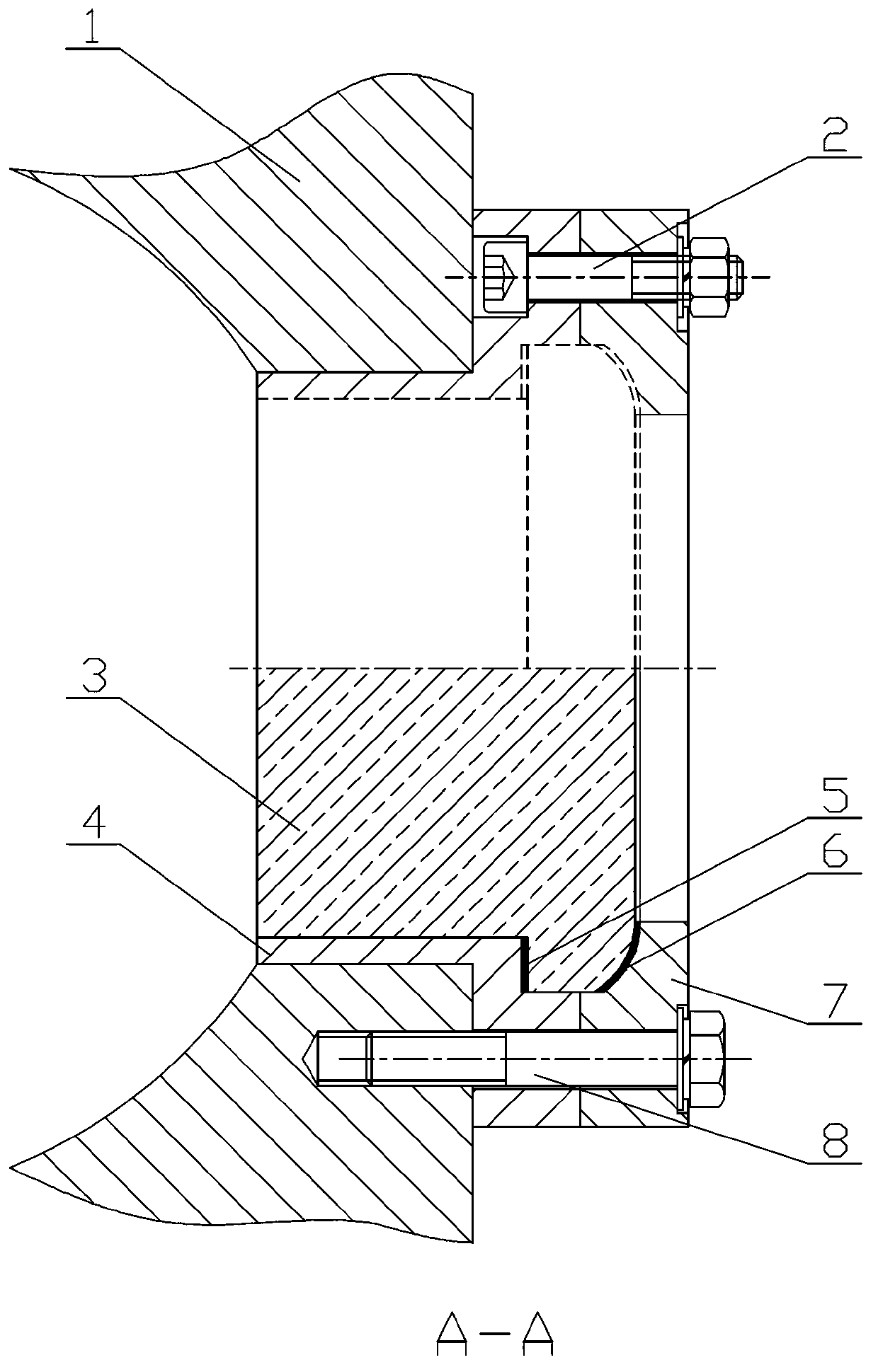
[0027] like figure 2 and image 3 As shown, this embodiment discloses a constant volume combustion device, the inner cavity of the combustion bomb body 1 adopts a spherical structure, and three observation holes in the shape of through holes are arranged on the combustion bomb body 1, and the observation holes are used for installing optical observation window. The optical observation window is mainly composed of an optical glass 3, an embedded end cover 4 and a compression end cover 7. The embedded end cover 4 and the compression end cover 7 are installed on the optical glass 3 and connected to each other through the M6 ​​inner hexagonal bolt 2, and then through The M8 outer hexagonal bolt 8 is integrally inst...


PUM


Abstract

The invention discloses a constant volume combustion device for observing the mutual effect of a flame and a pressure wave. A combustion bomb body is provided with an observation hole provided with an optical observation window; the optical observation window comprises optical glass provided with an annular boss on the outer side; the inner side and the outer side of the optical glass are respectively provided with an embedding end cover and a compressing end cover which are mutually connected through a bolt; the embedding end cover and the compressing end cover are arranged on the combustion bomb body through bolts; and high-temperature resistant gaskets are respectively arranged among the embedding end cover, the compressing end cover and the optical glass. According to the constant volume combustion device, the influence of the installation of the optical observation window of the combustion bomb body to the regularity of the inner cavity shape of the optical observation window is reduced, and the inner cavity smoothness is improved, so that the reflection effects of an inner flow field and a wall pressure wave are improved; and meanwhile, the stress manner of glass in the traditional optical observation window is changed, the thickness of the glass is reduced, and the device is beneficial to observation and shooting effects of experiments.

Description

technical field [0001] The invention relates to the technical field of internal combustion engine combustion, in particular to a constant volume incendiary bomb test device. Background technique [0002] The constant-volume incendiary bomb can simulate the constant-volume combustion process near the top dead center of the piston in the engine cylinder, and is generally used to observe the impact of changing the initial parameters of each test on the combustion process. In most cases, an optical observation window will be set on the projectile according to the experimental requirements, so that high-speed cameras can be used to observe internal spraying, flame propagation and other phenomena. The material of the observation window is mainly quartz glass, and sapphire glass is used in a few cases. However, even if the strength of glass with higher strength is more than ten times lower than that of steel, which is the main material of the incendiary projectile, the experimenta...

Claims


Application Information

Patent Timeline
Patent Type & Authority Applications(China)
IPC IPC(8): G01M15/04
Inventor 卫海桥蒋晟龙高东志舒歌群潘明章潘家营郭玉彬
Owner TIANJIN UNIV
Why Eureka
Try Eureka