

Voltage drop control method and device
A technology of voltage drop and control method, applied in the field of mobile power grid, which can solve the problems of large impulse voltage or impulse current, affecting the effect of low voltage ride-through test of wind power/photovoltaic system, etc.
- Summary
- Abstract
- Description
- Claims
- Application Information
AI Technical Summary
Problems solved by technology
Method used
Image

Examples
Embodiment 1
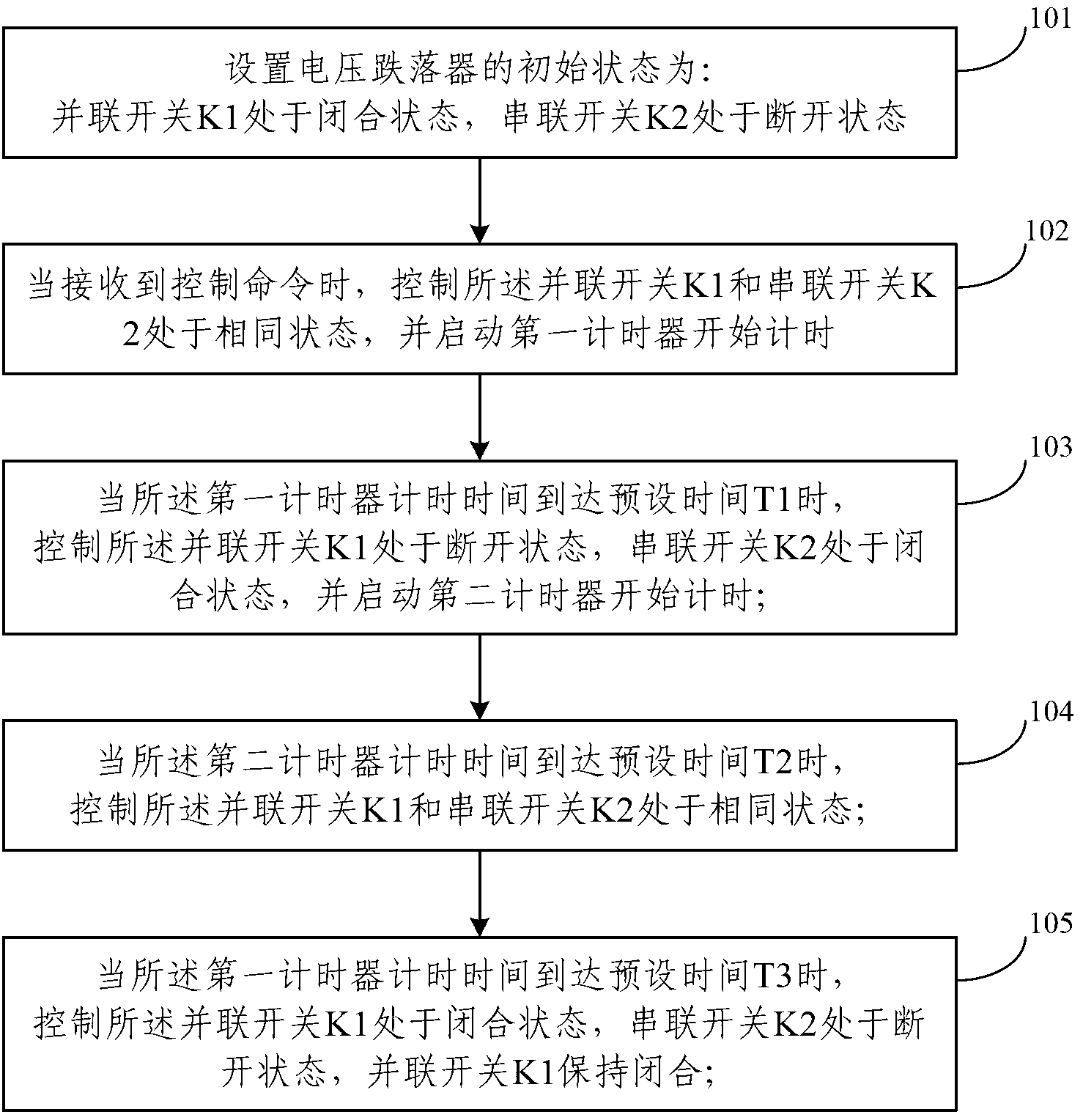
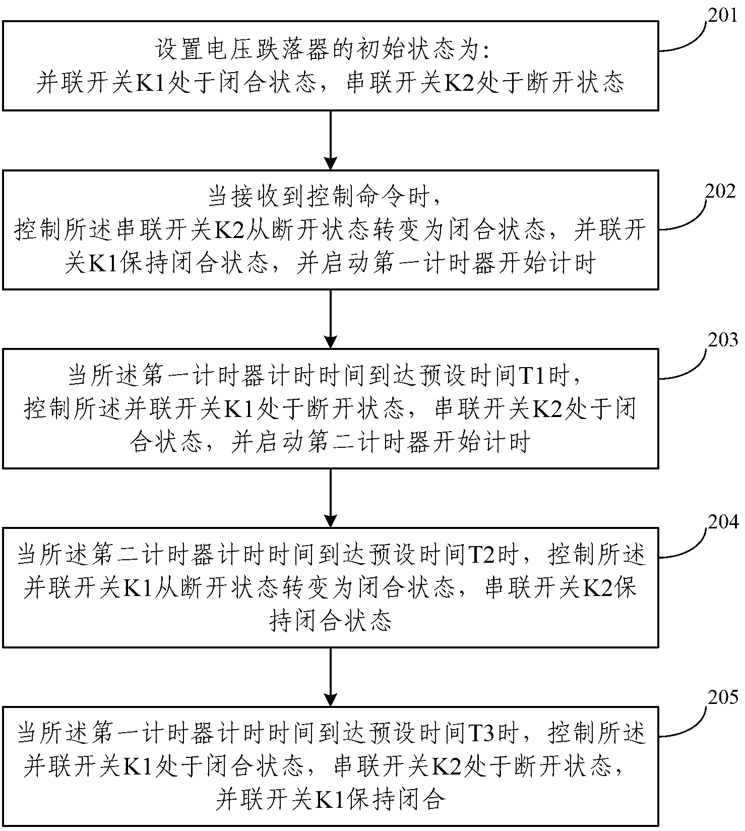
[0058] The present invention provides a voltage drop control method, the following is the description of Embodiment 1 as an example, please refer to figure 1 , which is a flow chart of a voltage drop control method disclosed in Embodiment 1 of the present invention, specifically including:
[0059] S101: set the initial state of the voltage drop device as follows: the parallel switch K1 is in the closed state, and the series switch K2 is in the open state;
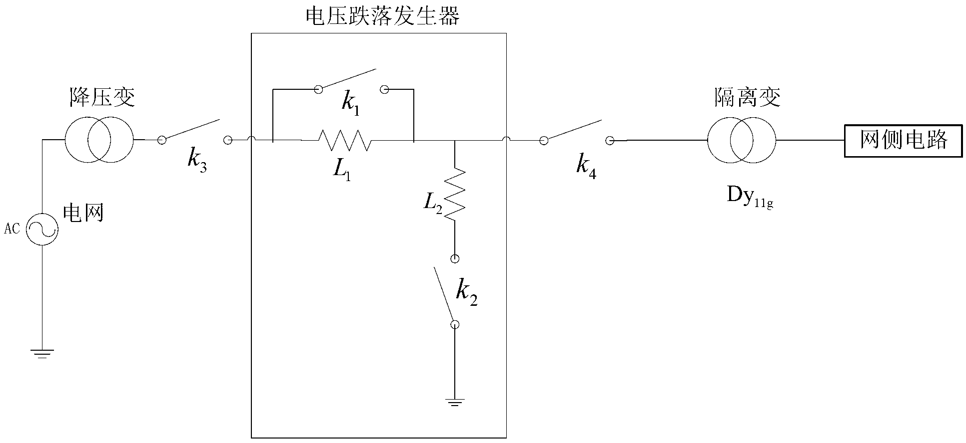
[0060] The main circuit topology diagram of the voltage drop generator based on the form of impedance division is as follows: figure 2 As shown, the specific working principle of the voltage drop generator is: through the appropriate matching of impedance L1 and impedance L2, the expected voltage drop function is realized; for example: open the circuit breaker K1 on the side of impedance L1, and open the circuit on the side of closed impedance L2 The circuit breaker K2 on the impedance L1 side closes the circuit breaker ...
Embodiment 2
[0076]In order to describe the control method provided by the present invention in more detail, a specific application scenario is taken as an example below. It should be noted that there are three-phase power grid voltage circuits in the voltage drop generator based on impedance division, respectively called A Phase circuit, B-phase circuit, and C-phase circuit, the preset control command in this embodiment is: act represents the value of the input control grid voltage drop type, when act is less than or equal to 0, the entire control method is not started, and the grid voltage In the normal state; when 0<act≤1, start to control the A-phase circuit to realize the voltage drop function; when 1<act≤2, start to control the A-phase circuit and B-phase circuit to realize the voltage drop function; when 2<act≤ At 3 o'clock, start and control the A, B, C three-phase circuits to jointly realize the voltage drop function. The value of Act can be set arbitrarily, and in this embodiment...
Embodiment 3
[0093] Correspondingly, the present invention also provides a voltage drop control device. The third embodiment is described below as an example. For details, please refer to Figure 4 A structural schematic diagram of a voltage drop control device is shown, specifically including:
[0094] The setting module 401 is used to set the initial state of the voltage dropper as follows: the parallel switch K1 is in the closed state, and the series switch K2 is in the open state;
[0095] A trigger module 402, configured to trigger a corresponding circuit to perform drop control according to the control command type;
[0096] The first control module 403 is configured to control the parallel switch K1 and the series switch K2 to be in the same state when receiving the control command, and start the first timer to start counting;
[0097] The second control module 404 is configured to control the parallel switch K1 to be in the off state and the series switch K2 to be in the closed st...
PUM
 Abstract
Description
Claims
Application Information