
Output power-based diagnosis method for open-circuit fault of insulated gate bipolar transistor (IGBT) of three-phase inverter

A technology for three-phase inverters and open-circuit faults, which is applied in the direction of instruments, measuring electrical variables, and measuring devices. It can solve problems such as motor load heating, misjudgment or missed judgment, and waveform distortion to ensure reliability and safety. Avoid the expansion of loss and reduce the effect of distortion

Inactive Publication Date: 2013-09-04
SOUTHWEST JIAOTONG UNIV
View PDF6 Cites 41 Cited by
  • Summary
  • Abstract
  • Description
  • Claims
  • Application Information

AI Technical Summary

Problems solved by technology

Since only two of the six IGBT power tubes or one IGBT power tube has an open-circuit fault, the motor or other loads can often continue to run, and it is not easy to be found; but it is very harmful, in which case the remaining IGBTs will flow If a larger current is passed, and the waveform is also greatly distorted, it will cause damage to the rest of the IGBT, and the motor or other loads will heat up. If it is not handled in time, it will cause a greater accident
[0003] At present, although some methods have been proposed for the open circuit fault of the power tube in the inverter, these methods are based on the distortion and offset characteristics of the current waveform after the fault to identify the fault, so they can only be used for a single IGBT Detection and location of open-circuit faults in power tubes. When open-circuit faults occur in any two IGBT power tubes, it will lead to misjudgment or missed judgment, so that timely and effective measures cannot be taken to avoid the expansion of losses and the occurrence of accidents.

Method used


Image

  • Output power-based diagnosis method for open-circuit fault of insulated gate bipolar transistor (IGBT) of three-phase inverter

Examples


Embodiment

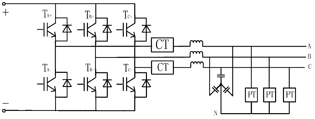
[0022] figure 1 Shown, a kind of embodiment of the present invention is, a kind of diagnosis method of IGBT open-circuit fault of three-phase inverter based on output power, its steps are as follows:

[0023] A. Calculate the power corresponding to the positive and negative half waves of each phase current

[0024] Measure the three-phase voltage u through the voltage transformer PT and current transformer CT installed in the output phase of the inverter a , u b , u c and three-phase current i a i b i c ; Use the discrete formula of power calculation to calculate the half-wave power P corresponding to the six half-wave currents in the three phases of the current cycle. a+ ,P a- ,P b+ ,P b- ,P c+ ,P c- ;

[0025] Where: P a+ Indicates the half-wave power corresponding to the positive half-wave current of phase A,

[0026] P a- Indicates the half-wave power corresponding to the negative half-wave current of phase A,

[0027] P b+ Indicates the half-wave power co...


PUM


Abstract

The invention discloses an output power-based diagnosis method for an open-circuit fault of an insulated gate bipolar transistor (IGBT) of a three-phase inverter. The method comprises the following steps of: A, respectively measuring three-phase voltages and three-phase currents by using a potential transformer (PT) and a current transformer (CT) installed on the output phase in the inverter, and respectively calculating the half-wave power corresponding to six half-wave currents of the three phases of the current period; and B, comparing the six half-wave power values with a set open-circuit fault power threshold value P0, if one or two half-wave power values are less than the set open-circuit fault power threshold value P0, judging that the corresponding IGBT causes an open-circuit fault; or if three half-wave power values are less than the set open-circuit fault power threshold value P0, judging that the IGBTs corresponding to the two half-wave power values on the same side cause the open-circuit fault. By the method, any one or two IGBTs which cause the open-circuit fault can be detected and positioned, so that a controller of the inverter can take a tolerance strategy and reduce waveform distortion conveniently; the inverter can be maintained in time; and the loss enlargement and accidents are avoided effectively.

Description

technical field [0001] The invention relates to a diagnosis of an open-circuit fault of a power tube in an inverter, and is especially suitable for various CVCF (constant voltage constant frequency) inverter power sources as the real-time detection and positioning of IGBT open-circuit faults, and at the same time as an inverter power supply Provides information on fail-safe and fault-tolerant controls. Background technique [0002] With the large-scale and wide application of inverter power supply, the reliability and safety of its work are gradually put on the agenda. If the abnormality of the inverter can be detected in time during operation and corresponding measures will be taken, the overall system will be significantly improved. level of safe and reliable operation. In the fault diagnosis of the inverter, there are mature and perfect solutions to the short-circuit fault of the IGBT power tube (insulated gate bipolar transistor), but there are not enough solutions for ...

Claims


Application Information

Patent Timeline
IPC IPC(8): G01R31/02
Inventor 何正友赏吴俊胡海涛母秀清
Owner SOUTHWEST JIAOTONG UNIV
Learn More