Fault monitoring method and device for brushless DC motor
A brushed DC motor and fault monitoring technology, applied in the direction of single motor speed/torque control, motor generator testing, etc., can solve the problems of secondary faults, small fault probability, and inability to monitor power tube faults in real time.
- Summary
- Abstract
- Description
- Claims
- Application Information
AI Technical Summary
Problems solved by technology
Method used
Image
Examples
Embodiment 1
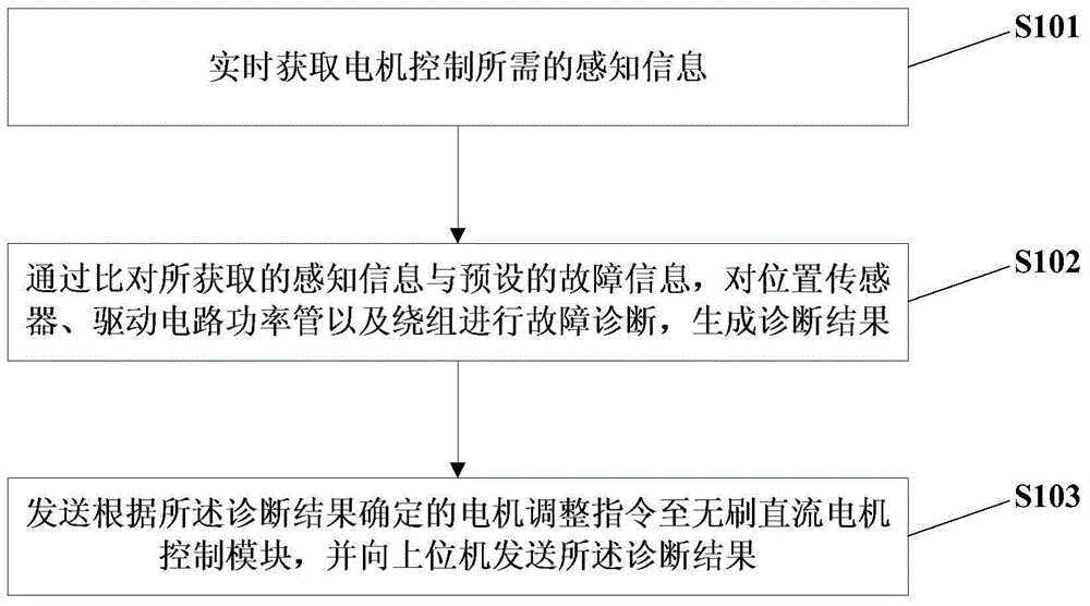
[0028] figure 1 The flow chart of the brushless DC motor fault monitoring method provided by Embodiment 1 of the present invention. This embodiment is applicable to the situation of online real-time monitoring of motor faults after the brushless DC motor is started. This method can be used by the brushless DC motor fault The monitoring device is implemented, and the device makes full use of the calculation and processing resources of the brushless DC motor control circuit microprocessor, and is set in the microprocessor of the control circuit in the form of a fault diagnosis module, specifically including the following steps:
[0029] S101. Obtain the sensing information required for motor control in real time.
[0030] Wherein, the sensing information includes bus current, winding current, and the relationship between the output signal of the position sensor and the working state of the motor. In terms of obtaining the sensing information, the signal acquisition source is co...
Embodiment 2
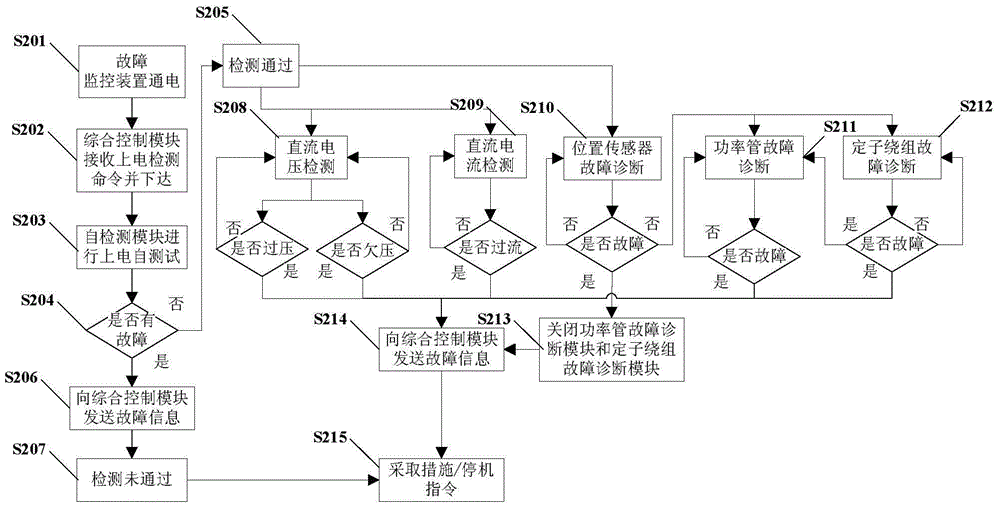
[0043] Figure 2a It is a flow chart of the brushless DC motor fault monitoring method in the second embodiment of the present invention. On the basis of the above technical solutions, each fault diagnosis module is further explained.
[0044] see Figure 2a and Figure 2b As shown, the brushless DC motor fault monitoring method specifically includes the following steps:
[0045] S201. The fault monitoring device is powered on.
[0046] S202. The comprehensive control module included in the fault monitoring device receives the power-on detection command sent by the host computer and sends it to the self-detection module. Among them, the integrated control module is used to receive external instructions, and obtain all the sensory information and distribute it to each fault diagnosis module, and make each fault diagnosis module work in coordination, and send health information to the host computer after forming a health conclusion. The integrated control module is also use...
Embodiment 3
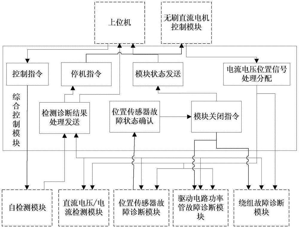
[0065] Figure 6 It is a structural schematic diagram of the brushless DC motor fault monitoring device in the third embodiment of the present invention. see Figure 6 As shown, the brushless DC motor fault monitoring device includes:
[0066] An information acquisition module 601, configured to acquire the sensory information required for motor control in real time;
[0067] The position sensor fault diagnosis module 602 is configured to perform fault diagnosis on the position sensor by comparing the acquired sensing information with preset fault information, and generate a diagnosis result;
[0068] The drive circuit power tube fault diagnosis module 603 is used to perform fault diagnosis on the drive circuit power tube by comparing the acquired sensing information with the preset fault information, and generate a diagnosis result;
[0069] The winding fault diagnosis module 604 is configured to perform fault diagnosis on the winding by comparing the acquired sensing info...
PUM
 Abstract
Description
Claims
Application Information
 - R&D
- Intellectual Property
- Life Sciences
- Materials
- Tech Scout
- Unparalleled Data Quality
- Higher Quality Content
- 60% Fewer Hallucinations
Browse by: Latest US Patents, China's latest patents, Technical Efficacy Thesaurus, Application Domain, Technology Topic, Popular Technical Reports.
© 2025 PatSnap. All rights reserved.Legal|Privacy policy|Modern Slavery Act Transparency Statement|Sitemap|About US| Contact US: help@patsnap.com


