Microwave photonic filter based on stimulated Brillouin scattering dynamic grating, and filtering method thereof

A technology of stimulated Brillouin and dynamic grating, applied in the fields of microwave photonics and optical communication, can solve the problems of non-reconfigurable microwave photonic filter, limited passband bandwidth, inability to continuously tune, etc., to achieve reconfigurable Effects of Features

Active Publication Date: 2013-09-04
HARBIN INST OF TECH
View PDF1 Cites 21 Cited by
  • Summary
  • Abstract
  • Description
  • Claims
  • Application Information

AI Technical Summary

Problems solved by technology

[0004] In order to solve the problem that the existing microwave photon filter cannot be reconfigured and continuously tuned, and the passband bandwidth

Method used


Image

  • Microwave photonic filter based on stimulated Brillouin scattering dynamic grating, and filtering method thereof
  • Microwave photonic filter based on stimulated Brillouin scattering dynamic grating, and filtering method thereof

Examples


specific Embodiment approach 1

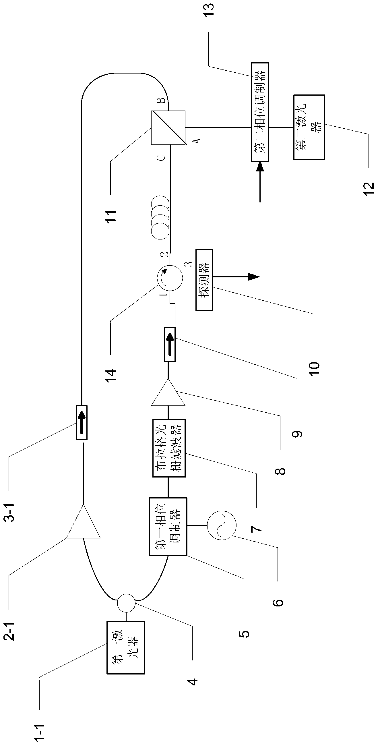
[0023] Specific implementation mode 1. Combination figure 1 Specifically illustrate this embodiment, the microwave photon filter based on stimulated Brillouin scattering dynamic grating described in this embodiment includes a first laser 1-1, a first erbium-doped fiber amplifier 2-1, a first isolator 3- 1. Fiber coupler 4, first phase modulator 5, microwave source 6, Bragg grating filter 7, second erbium-doped fiber amplifier 8, second isolator 9, detector 10, polarizing beam splitter 11, the first Two lasers 12, a second phase modulator 13 and a circulator 14,

[0024] The laser light emitted by the first laser 1-1 is divided into two laser beams through the fiber coupler 4, and the two laser beams are sent to the first erbium-doped fiber amplifier 2-1 and the first phase modulator 5 respectively,

[0025] The first erbium-doped fiber amplifier 2-1 amplifies the power of the received laser light to generate the first pump light, which is incident on the B port of the polari...

specific Embodiment approach 2

[0029] Embodiment 2. The difference between this embodiment and the microwave photon filter based on stimulated Brillouin scattering dynamic grating described in Embodiment 1 is that the first laser 1-1 and the second laser 12 are both Distributed feedback semiconductor lasers.

specific Embodiment approach 3

[0030] Embodiment 3. The difference between this embodiment and the microwave photon filter based on the stimulated Brillouin scattering dynamic grating described in Embodiment 1 is that the optical splitting ratio of the fiber coupler 4 is 1:1.

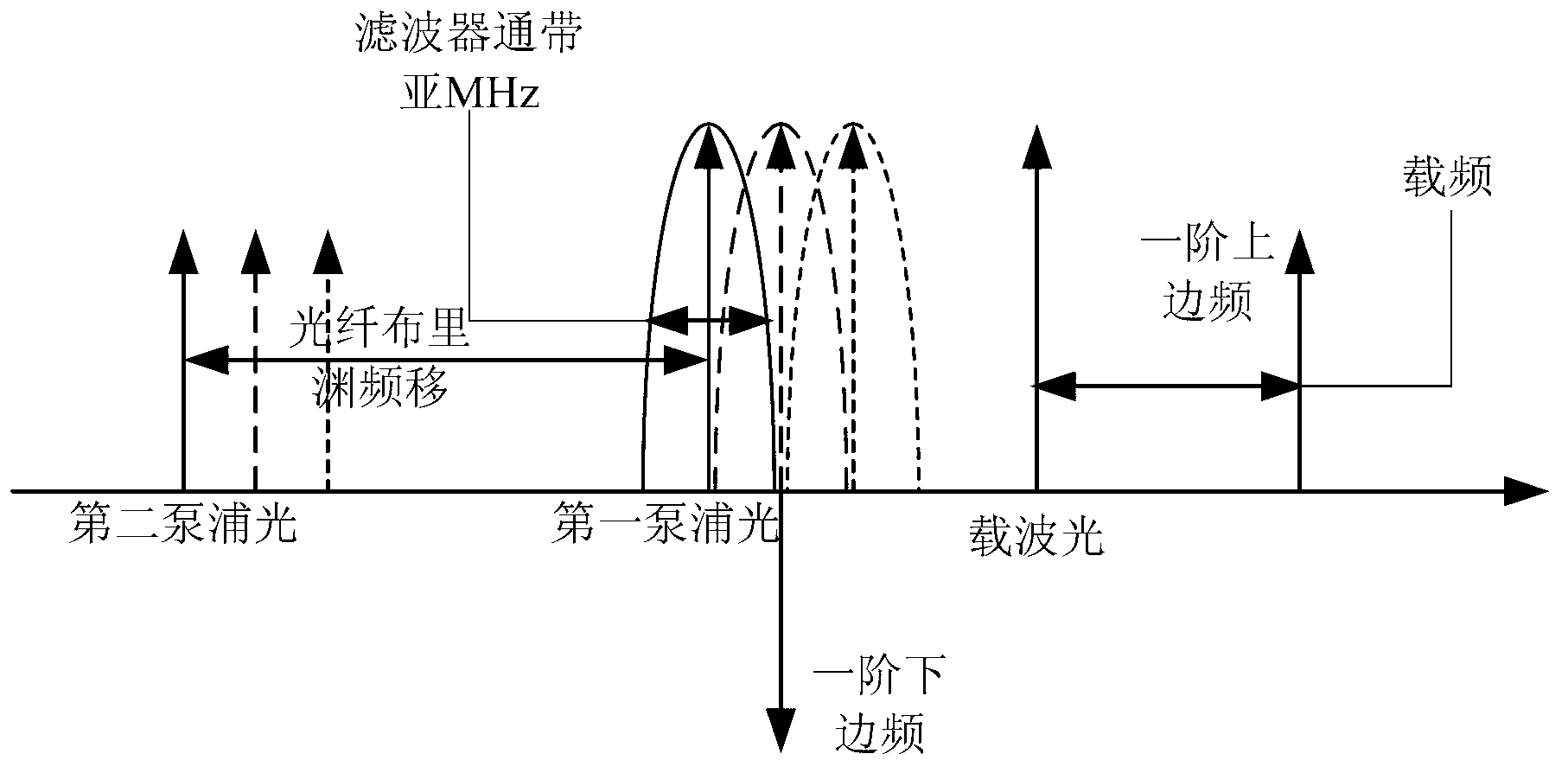
[0031] In this embodiment, the first laser 1-1 is used as a pumping light source, and the frequency is v p , split into two paths through the 50%:50% fiber coupler 4, the upper branch is used as the first pump light, the frequency is v p , providing energy, the lower branch as the second pump light is Stokes light with frequency v p -v B , the two enter the optical fiber to generate stimulated Brillouin scattering (SBS), forming a dynamic grating (BDG) based on stimulated Brillouin scattering. The second laser 12 outputs light as carrier light in the 155Onm waveband.

[0032] The first pumping light is continuous light, which is amplified through the first erbium-doped fiber amplifier 2-1 (EDFA), and the first isolator 3-1 prevents ...


PUM


Abstract

The invention relates to a microwave photonic filter based on a stimulated Brillouin scattering dynamic grating, and a filtering method thereof, and solves the problem that the existing microwave photonic filter is non-reconstructable and unavailable for continuous tuning and has limited pass bandwidth. The microwave photonic filer comprises a first laser, a first Er-doped fiber amplifier, a first isolator, a fiber coupler, a first phase modulator, a microwave source, a Bragg grating filter, a second Er-doped fiber amplifier, a second isolator, a detector, a polarized light splitter, a second laser, a second phase modulator, and a circulator. The filtering method includes: loading microwave signals to be filtered to carrier light transmitted by the second laser, allowing the detector to output the microwave signals after the loaded carrier light passes the Brillouin dynamic grating, and finishing filtering based on the stimulated Brillouin scattering dynamic grating. The microwave photonic filter based on a stimulated Brillouin scattering dynamic grating, and the filtering method thereof are applicable to the microwave photonics field and the photo-communication field.

Description

technical field [0001] The invention relates to a microwave photon filter based on a stimulated Brillouin scattering dynamic grating and a filtering method thereof, belonging to the fields of microwave photonics and optical communication. Background technique [0002] Traditional filtering technology uses a large number of electronic circuits to process microwave signals, and the system is complex and susceptible to electromagnetic interference. With the continuous development of optical fiber communication all-optical network construction and high communication capacity, traditional filters are no longer suitable. The microwave photonic filter directly modulates the optical carrier by the microwave signal, and uses the optical method to process the microwave signal in the optical domain. The filter uses optical fibers, optical amplifiers, couplers, etc., and has the characteristics of high bandwidth, low loss, compact structure, small size, light weight, strong anti-electr...

Claims


Application Information

Patent Timeline
IPC IPC(8): G02F1/01H04B10/2537
Inventor 董永康周登望姜桃飞吕志伟
Owner HARBIN INST OF TECH
Why Eureka
Try Eureka