
Self-correcting electron beam scanning output system

A technology of electron beam scanning and output system, applied in general control system, control/adjustment system, instrument, etc., can solve the problems of inconsistent dose, dose reduction, etc., and achieve the effect of solving the problem of uniformity

Active Publication Date: 2016-06-29
SHANDONG LANFU HIGH ENERGY PHYSICS TECH CO LTD
View PDF6 Cites 0 Cited by
  • Summary
  • Abstract
  • Description
  • Claims
  • Application Information

AI Technical Summary

Problems solved by technology

[0003] Although the above scheme can realize the left and right swing of the electron beam, since the energy of the electron beam is directly related to the irradiation time of the electron beam
When the electron beam is deflected to both ends of the scanning box, under the same angular velocity, the time for the goods per unit area to be irradiated will be reduced, so that the dose will be reduced, resulting in inconsistent doses between the middle of the goods and the two ends of the goods

Method used


Image

  • Self-correcting electron beam scanning output system

Examples


Embodiment Construction

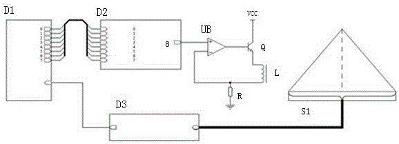
[0018] See attached figure 1 , the present invention is made up of following several parts, 1. single-chip microcomputer system. The single-chip microcomputer system includes single-chip microcomputer, power supply circuit, oscillation circuit, protection circuit and other necessary peripheral circuits to ensure the long-term and stable operation of the single-chip microcomputer. 2. D / A conversion unit. The D / A conversion unit is mainly a D / A conversion chip and peripheral circuits required by the D / A conversion chip. The D / A conversion unit can convert the digital quantity output by the microcontroller into an analog quantity, that is, output the appropriate waveform required by the scanning power supply. 3. Amplifying circuit unit. The amplifying circuit unit completes the adjustment of the D / A output waveform, so that its amplitude can meet the actual scanning requirements. 4. Power amplification unit. The power amplifying unit can amplify the power of the waveform out...


PUM


Abstract

The invention relates to a self-correction electron beam scanning output system, which comprises a single chip system, a D / A (digital / analog) conversion unit, an amplification circuit unit, a power amplification unit, a dose sensor unit and a dose signal processing unit. The self-correction electron beam scanning output system can overcome the defect of the prior art that the scanning degree is non-uniform, a negative feedback mechanism under the large-power amplification circuit and a real-time monitoring and feedback mechanism of the scanning dose are adopted, the correction is carried out according to the real dose and the set dose, so that the irradiation dose on each part of a cargo in scanning is in consistency.

Description

technical field [0001] The invention relates to a measuring and testing device, in particular to an electron beam scanning measuring and testing device. Background technique [0002] According to the analysis of the movement mode of the electron beam in the magnetic field, the original scanning power supply adopts the triangular wave mode, so that the electron beam swings left and right under the action of the changing magnetic field. The specific implementation method is to use an integrated signal generator to generate a fixed frequency and fixed amplitude triangular wave. The triangular wave is adjusted to a suitable amplitude after being processed by the amplifier circuit, and then output through the operational amplifier and power amplifier circuit. At the same time, the actual waveform is fed back to the Op amp negative terminal. [0003] Although the above solution can realize the left and right swing of the electron beam, the energy of the electron beam is directly ...

Claims


Application Information

Patent Timeline
Patent Type & Authority Patents(China)
IPC IPC(8): G05B19/042
Inventor 黄忠义沈松陈光荣王文兵位同厦巩新胜徐建慧吕荣伟
Owner SHANDONG LANFU HIGH ENERGY PHYSICS TECH CO LTD
Learn More