Co-extrusion molding optical film equipment

A technology of co-extrusion molding and optical film, which is applied in the field of optical film, can solve the problems of uneven forming of optical film, easy formation of concave and convex points on optical film, easy sticking of glue, etc.

Active Publication Date: 2022-07-29
NANJING BREADY ELECTRONICS CO LTD
View PDF7 Cites 0 Cited by
  • Summary
  • Abstract
  • Description
  • Claims
  • Application Information

AI Technical Summary

Problems solved by technology

[0003] For example, a co-extrusion forming optical film equipment disclosed in Chinese patent CN201720710105.5 includes a fixed base, an extrusion molding mechanism, a forming extrusion roller set, a shaping roller set, a traction pressure roller set, an edge material cutting mechanism, a tension wheel, Laminating wheel set, protective film feeding shaft and main receiving shaft; extrusion forming mechanism, forming extrusion roller set, shaping roller set, traction pressing wheel set, edge material cutting mechanism, tension wheel, laminating wheel set and main The receiving shaft is sequentially set on the fixed base along the material output direction, and the protective film discharging shaft is set on the fixed base. The protective film discharging shaft is located between the tension wheel and the laminating wheel set. The cooperation of the roller group and the shaping roller group forms the liquid material into an optical film, which is pulled and transported by means of roller connection, but in this way, it is very easy to cause uneven formation of the optical film, and glue, etc. are easy to stick to the rollers , leading to easy formation of concave and convex points on the surface of the optical film

Method used


Image

  • Co-extrusion molding optical film equipment
  • Co-extrusion molding optical film equipment
  • Co-extrusion molding optical film equipment

Examples


Embodiment Construction

[0030] The technical solutions in the embodiments of the present invention will be clearly and completely described below with reference to the accompanying drawings in the embodiments of the present invention. Obviously, the described embodiments are only a part of the embodiments of the present invention, rather than all the embodiments. Based on the embodiments of the present invention, all other embodiments obtained by those of ordinary skill in the art without creative efforts shall fall within the protection scope of the present invention.

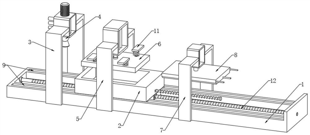
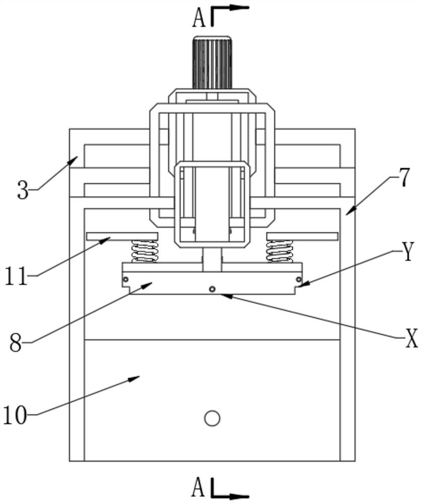
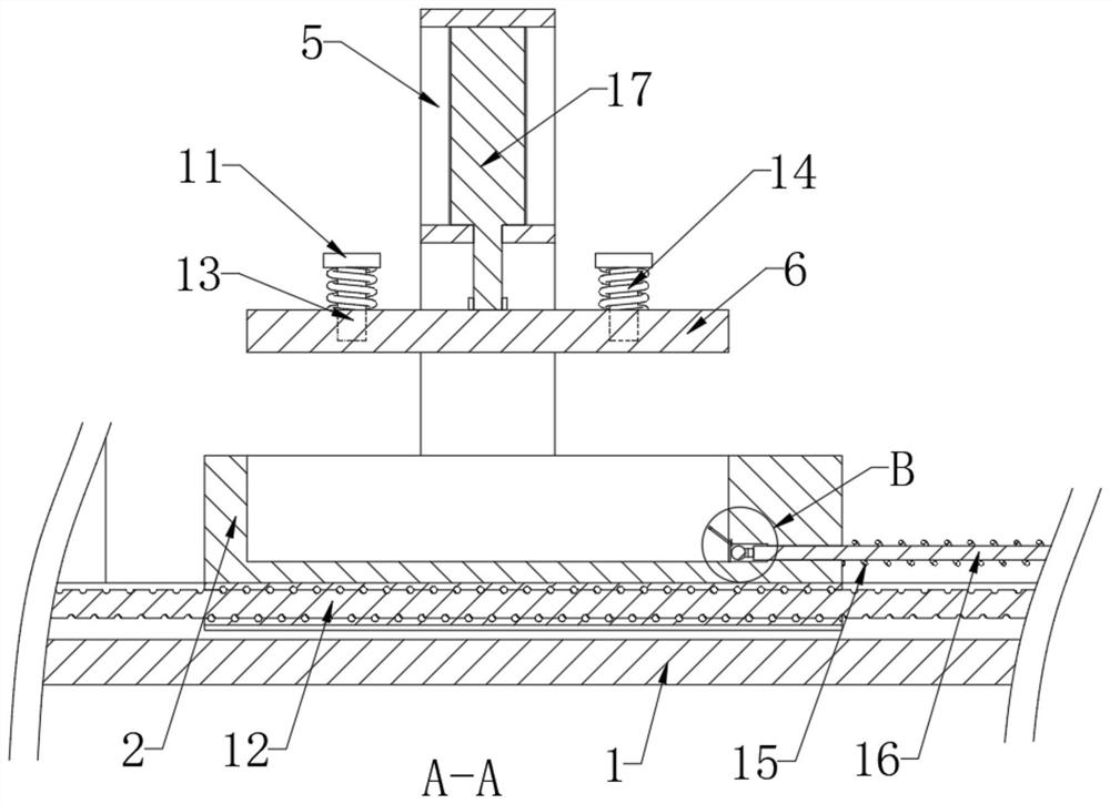
[0031] see Figure 1 to Figure 9, the present invention provides a technical solution: a co-extrusion molding optical film equipment, including a sliding table 1 and a co-extrusion device, a molding table 2 is slidably connected to the sliding table 1, and a molding groove is opened inside the molding table 2. The molding groove The inner bottom is a smooth plane, and the co-extrusion device can output the finished material into the ...


PUM


Abstract

The invention discloses co-extrusion forming optical film equipment which comprises a sliding table and a co-extrusion device, a forming table is slidably connected to the sliding table, a forming groove is formed in the forming table, the inner bottom of the forming groove is a smooth plane, the co-extrusion device can output finished product materials into the forming groove, a second portal frame is fixed to the sliding table, and a second portal frame is fixed to the second portal frame. A first air cylinder is fixedly installed on the second portal frame, the output end of the first air cylinder is fixedly connected with a first forming module, the bottom of the first forming module is equal to the inner bottom of the forming groove, and the first forming module moves downwards and can enter and seal the forming groove; according to the extrusion forming device, the co-extruded optical film material can be subjected to extrusion forming in the forming groove, and after the optical film is formed, a boundary protection coating and a protection surface layer can be formed on the upper surface of the optical film.

Description

technical field [0001] The invention relates to the technical field of optical films, in particular to a co-extrusion molding optical film equipment. Background technique [0002] Optical films generally include antireflection films, reflective films and light enhancement films, which are commonly used in the optical field. Multilayer optical films are usually formed by layering co-extruded polymers in a feed zone. [0003] For example, a co-extrusion forming optical film equipment disclosed in Chinese patent CN201720710105.5 includes a fixed base, an extrusion forming mechanism, a forming extrusion roller group, a shaping roller group, a traction pressing Laminating wheel set, protective film feeding shaft and main receiving shaft; extrusion molding mechanism, forming extrusion roller set, shaping roller set, traction pressing wheel set, edge material cutting mechanism, tension wheel, laminating wheel set and main The take-up shaft is set on the fixed base in turn along th...

Claims


Application Information

Patent Timeline
Patent Type & Authority Applications(China)
IPC IPC(8): B29C43/04B29C43/32B29C43/34B29C43/36B29C43/52B29L11/00
CPCB29C43/04B29C43/32B29C43/34B29C43/36B29C43/52B29C2043/3433B29L2011/00
Inventor 刘勇张威李永刚
Owner NANJING BREADY ELECTRONICS CO LTD
Why Eureka
Try Eureka