Paralleling reactor compensation loop of transformer substation and compensation method of paralleling reactor compensation loop of transformer substation

A technology of compensation circuit and reactor, which is applied in the direction of emergency protection circuit device, reactive power compensation, circuit device, etc. for limiting overcurrent/overvoltage, and can solve bus side oscillation, bus short circuit, bus voltage change high voltage fuse Fuse and other problems to achieve the effect of protecting system safety, reducing overvoltage, and increasing system capacitance to ground

Active Publication Date: 2013-09-04
STATE GRID CORP OF CHINA +2
View PDF6 Cites 2 Cited by
  • Summary
  • Abstract
  • Description
  • Claims
  • Application Information

AI Technical Summary

Problems solved by technology

[0005] When the vacuum circuit breaker breaks and resists such small inductive loads, the first open phase will have different degrees of cut-off, which will cause overvoltage on the load side and cause re-ignition of the first open phase. Due to continuous re-ignition and inter-phase coupling, the second two phases will be equal Effective cut-off, causing more serious overvoltage on the load side, leading to and resisting faults such as inter-turn breakdown or even burning
If the system is an empty bus with no load, due to the small capacitance of the bus side to the ground, the bus side will also oscillate and cause serious overvoltage, which will cause damage to the transformer on the bus side or blown high-voltage fuses, and blown high-voltage fuses on the busbar side , or even a direct short-circuit of the busbar, which seriously affects the normal operation of the 35kV parallel reactance and system safety

Method used


Image

  • Paralleling reactor compensation loop of transformer substation and compensation method of paralleling reactor compensation loop of transformer substation

Examples


Embodiment 1

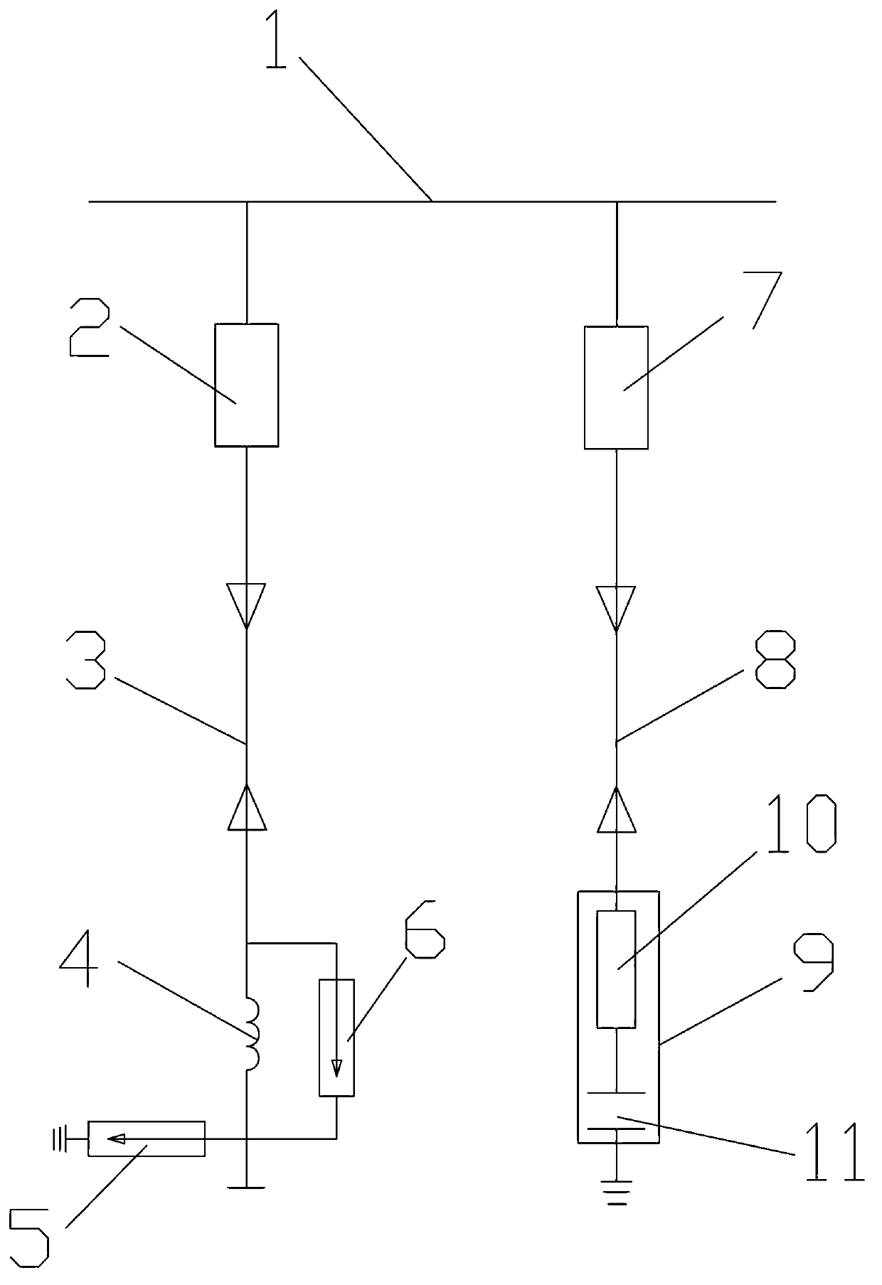
[0022] Such as figure 1 As shown, a shunt reactor compensation circuit of a substation provided in this embodiment includes an empty bus 1, and the empty bus 1 is respectively connected to the first switch 2 of the vacuum circuit breaker and the second switch 7 of the vacuum circuit breaker; Wherein the first switch 2 of the vacuum circuit breaker is connected to one end of the shunt reactor 4 through the first cable 3, and the other end of the shunt reactor 4 is three-phase short-circuited as a neutral point; the shunt reactor 4 and the turns The inter-turn arrester 6 is connected in parallel, one end of the turn-to-turn arrester 6 is connected to the arrester 5 circuit, and the other end of the arrester 5 is grounded; the second switch 7 of the vacuum circuit breaker is connected to the RC absorber 9 circuit through the second cable 8 connected, and the other end of the RC absorber 9 is grounded.

[0023] The RC absorber 9 includes a 20Ω resistor 10 and a 0.2 μF capacitor 1...

Embodiment 2

[0031] Such as figure 1 As shown, the shunt reactor compensation circuit of a substation provided by this embodiment includes an empty bus 1, and the empty bus 1 is connected to the first switch 2 of the SF6 circuit breaker and the second switch 7 of the SF6 circuit breaker respectively; Wherein the first switch 2 of the SF6 circuit breaker is connected to one end of the shunt reactor 4 through the first cable 3, and the other end of the shunt reactor 4 is three-phase short-circuited as a neutral point; the shunt reactor 4 and the turns Inter-turn arrester 6 is connected in parallel, one end of said turn-to-turn arrester 6 is connected to arrester 5 circuit, and the other end of said arrester 5 is grounded; the second switch 7 of said SF6 circuit breaker passes second cable 8 and RC absorber 9 circuit connected, and the other end of the RC absorber 9 is grounded.

[0032] Described RC absorber 9 comprises the electric capacity 11 of the resistance 10 of 50 Ω, 0.6 μ F, the res...


PUM


Abstract

The invention discloses a paralleling reactor compensation loop of a transformer substation and a compensation method of the paralleling reactor compensation loop of the transformer substation. The paralleling reactor compensation loop comprises an empty bus which is connected with a first switch and a second switch in a circuited mode. The first switch is connected with one end of a paralleling reactor through a first cable. The other end of the paralleling reactor undergoes three-phase short circuit and is a neutral point. The paralleling reactor is connected with a turn-to-turn arrester in parallel. One end of the turn-to-turn arrester is connected with a circuit of the arrester and the other end of the arrester is connected to the ground. The second switch is connected with a circuit of an MCR-P through a second cable. The other end of the MCR-P is connected to the ground. The invention provides the paralleling reactor compensation loop of the transformer substation and the compensation method of the paralleling reactor compensation loop. As the MCR-P is added on the system empty bus and two ends of the electric reactor are connected with the turn-to-turn arrester in parallel, overvoltage of the bus and one side of a load can be reduced when the paralleling reactor is switched and safety of the paralleling reactor and a system can be ensured.

Description

[0001] technical field [0002] The invention relates to a compensation circuit and a compensation method thereof, in particular to a compensation circuit of a shunt reactor of a substation and a compensation method thereof. [0003] Background technique [0004] In order to adjust the voltage and reactive power, for the 220kV substation whose 110kV outgoing line is a cable, the current power grid generally configures a shunt reactor on the 35kV side, and the switching equipment generally uses a vacuum circuit breaker, which is installed in the switch room. type reactor, dry-type air-core reactor, etc.) are generally installed outdoors, and the switching equipment is connected to the shunt reactor through a long cable. [0005] When the vacuum circuit breaker breaks and resists such small inductive loads, the first open phase will have different degrees of cut-off, which will cause overvoltage on the load side and cause re-ignition of the first open phase. Due to continuous...

Claims


Application Information

Patent Timeline
Patent Type & Authority Applications(China)
IPC IPC(8): H02J3/18H02J3/12H02H9/06
CPCY02E40/30
Inventor 李电金百荣胡雪平陈晓宇蔡重凯李云飞洪金琪秋勇吕丹
Owner STATE GRID CORP OF CHINA
Why Eureka
Try Eureka