Intelligent charging device suitable for AGV guiding vehicle

A charging device and guided vehicle technology, applied in the direction of circuit devices, battery circuit devices, collectors, etc., can solve problems such as easy adsorption of foreign matter, manual intervention, brush block wear, etc., to achieve safe and reliable work, high degree of automation, and simple structure reasonable effect

Inactive Publication Date: 2013-09-04
HUBEI SANFENG ROBOT CO LTD
View PDF4 Cites 14 Cited by
  • Summary
  • Abstract
  • Description
  • Claims
  • Application Information

AI Technical Summary

Problems solved by technology

The disadvantage of the charging device used in the first method is that manual intervention is required
Although the charging device of the second method has a relatively high degree of automation, its disadvantage is that the foundation needs to be excavated on the ground, which cannot be implemented on the ground of the workshop where excavation is not allowed; in addition, the conductive plate is buried underground, and insulation treatment requirements High, if the ground encounters a humid climate, it is easy to cause leakage between the positive and negative conductive plates, and the brush block is easy to wear and absorb foreign matter, resulting in poor contact between the worn and absorbed foreign matter and the conductive plate. Discharge sparks together

Method used


Image

  • Intelligent charging device suitable for AGV guiding vehicle
  • Intelligent charging device suitable for AGV guiding vehicle
  • Intelligent charging device suitable for AGV guiding vehicle

Examples


Embodiment 1

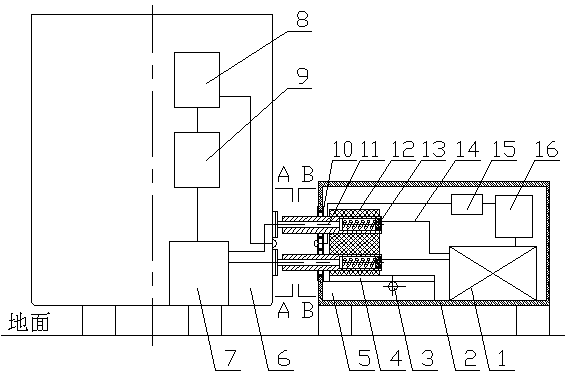
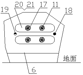
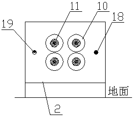
[0019] The structure of the charger 2: a printed circuit board, a transformer and a charging contact telescopic structure are installed in the chassis; the printed circuit mainly includes a charging control module 1, a charger signal transceiver device 15, a charger control main board 16 and an AC / DC conversion module; The main structure of the telescopic structure of the charging contact is: the charging output end 11 is a contact structure, the charging output end 11 is installed on the sliding platform 4 through the insulator 12, the sliding platform 4 is installed on the sliding guide rail 5 and equipped with a sliding driving mechanism 3, sliding The driving mechanism 3 is a rack and pinion transmission mechanism and equipped with a stepping motor, and the electric control part of the stepping motor is electrically connected with the charging control module 1 . The charging output terminal 11 is electrically connected to the charging control module 1 through a cable 14 . ...

Embodiment 2

[0022] It is basically the same as the embodiment, except that a contact sleeve 17 is arranged between the charging output end 11 and the insulator 12 , and a compression spring 13 is installed between the charging output end 11 and the contact sleeve 17 .

Embodiment 3、4

[0024] On the basis of Embodiments 1 and 2 respectively, the sliding drive mechanism 3 is a rack and pinion transmission mechanism and equipped with a stepping motor, and the electrical control part of the stepping motor is electrically connected to the charging control module 1 .


PUM


Abstract

The invention discloses an intelligent charging device suitable for an AVG guiding vehicle. The charging device comprises a charger. The charger mainly comprises a charging control module, a charging output end and a charger control main board. The charging output end is of a contact type structure and can be electrically connected with a charging pole plate installed on the AVG guiding vehicle in a contacted mode, and the charging pole plate is electrically connected with a storage battery on the AVG guiding vehicle. The charging output end is installed on a sliding platform through an insulator, and the sliding platform is installed on a sliding guide rail and configures a sliding drive mechanism. The side face, facing towards the AVG guiding vehicle, of the charger is provided with an emitter and a receiver, the side face, corresponding to the charger, of the AVG guiding vehicle is provided with an emitter and a receiver in a pairing mode. The emitter and the receiver on the charger are electrically connected with the charging control module through a charger signal transmitter-receiver device. The emitter and the receiver on the ACG guiding vehicle are electrically connected with a battery monitoring device through a trolley signal transmitter-receiver device.

Description

technical field [0001] The invention relates to an intelligent charging device suitable for an AGV guided vehicle. Background technique [0002] At present, there are basically two online charging methods for AGV guided vehicles. The first method is to manually connect the charger to the battery of the AGV guided vehicle through a plug socket for charging. The second method is to install a conductive plate on the ground, and the conductive plate is connected to charge. The positive and negative poles of the device, the brush block that matches the conductive plate is installed under the AGV guided vehicle, and the brush block of the AGV guided vehicle can be charged after matching the conductive plate on the ground, and the AGV guided vehicle can leave after charging. The disadvantage of the charging device used in the first method is that manual intervention is required. Although the charging device of the second method has a relatively high degree of automation, its disad...

Claims


Application Information

Patent Timeline
Patent Type & Authority Applications(China)
IPC IPC(8): H02J7/00
Inventor 袁志勇
Owner HUBEI SANFENG ROBOT CO LTD
Why Eureka
Try Eureka