
Patsnap Eureka
For R&D, Patsnap Eureka makes reading and utilizing patents & technical documents easy.
Patsnap Eureka AIR
Designed for self-driven R&D workflows. Generate viable solutions, solve complex R&D challenges, empower your innovation with AI.

Patsnap Eureka Materials
Designed for material experts only. Revolutionize your material R&D, from search, analyze, to developing new materials.

TechResearch
Generate reliable direction feasibility study reports for your R&D in just a few steps.

TechSeek
Discover and master advanced knowledge NOW. Basics, ideas, possibilities, all at once.

TechMind
As an expert in R&D Theories, TechMind can generates customized viable solutions instantly.

TechRisk
Analyze your overall solution with one click, know your potential R&D risks in advance.

TechMonitor
Get weekly tech updates, stay abreast of the latest tech innovations and key insights.
X-ray CT system and control program
An X-ray and X-ray tube technology, applied in the field of X-ray CT device and its control, can solve the problems of inability to obtain high resolution and inability to make full use of detection
- Summary
- Abstract
- Description
- Claims
- Application Information
AI Technical Summary
Problems solved by technology
Method used
Image

Examples
no. 1 Embodiment approach
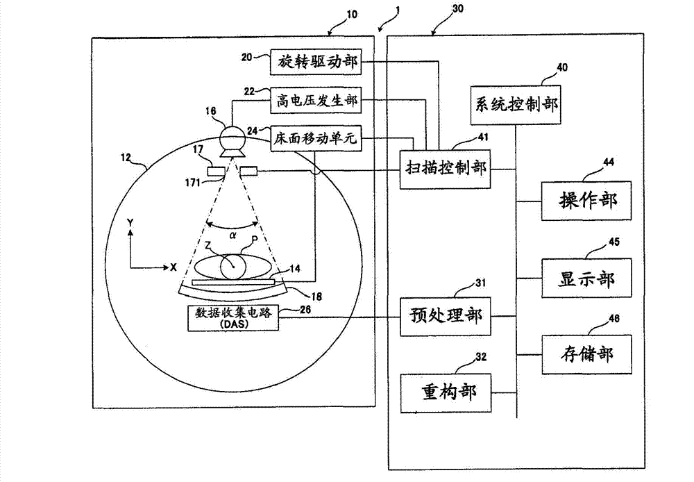
[0043] refer to figure 1 , and the configuration of the X-ray CT apparatus according to the first embodiment will be described. figure 1 It is a block diagram showing the configuration of the X-ray CT apparatus.
[0044] like figure 1 As shown, the X-ray CT apparatus 1 has a gantry (gantry) 10 and a console 30 .
[0045] 〔shelf〕
[0046] The gantry 10 has a rotating frame 12 , an X-ray tube 16 , a collimator 17 , an X-ray detector 18 , a rotation driving unit 20 , a high voltage generating unit 22 , and a data acquisition circuit (DAS) 26 .
[0047] The main body of the stand 10 rotatably supports a circular or disk-shaped rotating frame 12 . On the inner peripheral side of the rotating frame 12, a scanning area where the subject P placed on the bed surface 14 is inserted is formed.
[0048] For a bed not shown, a bed surface moving unit 24 is provided to move the bed surface 14 in the longitudinal direction (the body axis direction of the subject P). In addition, the be...
no. 2 Embodiment approach
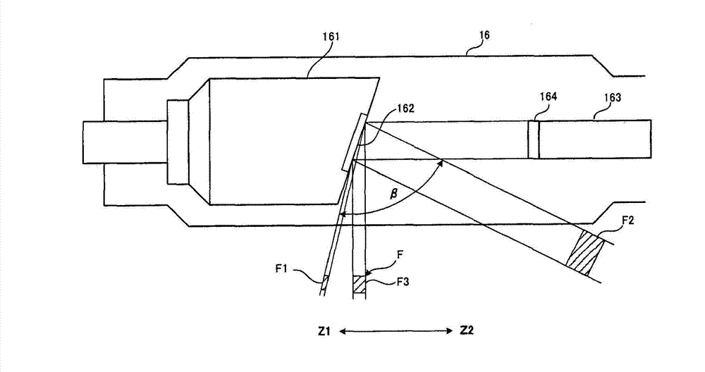
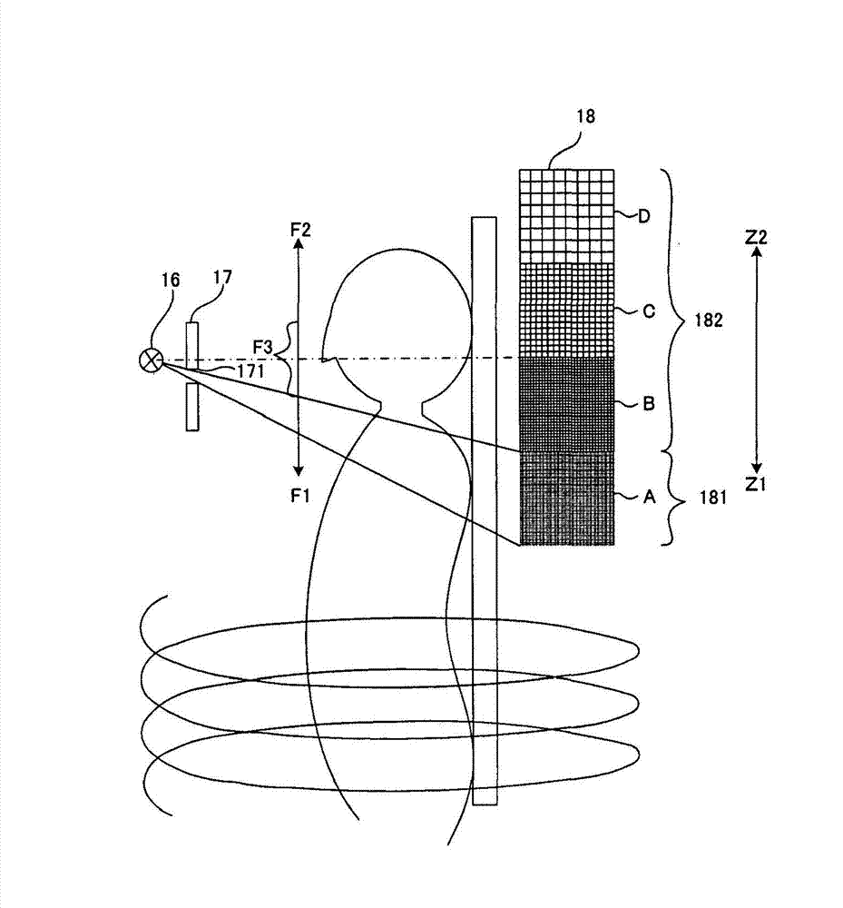
[0165] In the first embodiment, as the scan mode, the first mode in which the small detection range 181 is associated with the focal point F1 having a small focal size to perform CT scanning, and the large detection range 182 and the focal point F2 with a large focal size have been described. Or the second mode in which CT scanning is performed corresponding to the focal point F3 of the medium focal point size. According to the first mode, it is possible to shoot at high resolution. In addition, according to the second mode, imaging can be performed at a desired level of resolution, and imaging of the subject can be performed over a wide range.
[0166] In addition to the first mode and the second mode, in the scan mode, there is also a third mode in which CT scanning is performed using all of the X-ray detectors 18 . By adopting the third mode, projection data photographed at high resolution and projection data photographed at low resolution can be obtained simultaneously, a...
no. 3 Embodiment approach
[0198] Next, refer to Figure 16 as well as Figure 17 , the X-ray CT apparatus 1 according to the third embodiment will be described. In the above-mentioned third embodiment, configurations different from those in the above-mentioned embodiment will be mainly described, and the same configurations will be given the same reference numerals and their descriptions will be omitted.
[0199] In the X-ray CT apparatus 1 of the above-mentioned embodiment, when X-ray imaging is performed, the X-ray tube 16 and the X-ray detector 18 are rotated around the body axis, and the bed surface 14 is moved in the direction of the body axis while performing helical scanning. , by controlling the collimator 17 with the control unit, from effective focal points of different sizes to a specified detection area including a small detection range 181 of a small size and a large detection range 182 of a large size by making the X-ray detection element different in size, By irradiating X-rays, desire...
PUM
 Abstract
Description
Claims
Application Information
 - R&D Engineer
- R&D Manager
- IP Professional
- Industry Leading Data Capabilities
- Powerful AI technology
- Patent DNA Extraction
Browse by: Latest US Patents, China's latest patents, Technical Efficacy Thesaurus, Application Domain, Technology Topic, Popular Technical Reports.
© 2024 PatSnap. All rights reserved.Legal|Privacy policy|Modern Slavery Act Transparency Statement|Sitemap|About US| Contact US: help@patsnap.com