
Water pressure torsional impact device for well drilling

A technology of impact device and hydraulic pressure, which is applied to the driving device for drilling in the borehole, drilling equipment, earthwork drilling and production, etc., which can solve the adverse effects of drill bit sticking, drill bit, drill string supporting parts service life, and many wearing parts And other issues

Active Publication Date: 2013-09-11
WENZHOU JIADA MACHINERY MFG
View PDF6 Cites 26 Cited by
  • Summary
  • Abstract
  • Description
  • Claims
  • Application Information

AI Technical Summary

Problems solved by technology

[0002] The existing drill bits have the following problems in the use process: (1) During the drilling process, the drill bit usually has sticking, slipping, and drill sticking phenomena, and the drill string is always tightened like a clockwork, and it is released quickly after the torque is accumulated. , this kind of engineering problem is more serious, the torsional vibration of the drill string makes the whole drilling process unstable, and has an adverse effect on the service life of the drill bit and the supporting parts of the drill string
(2) For hard formations or abrasive formations, the drilling depth of the drill bit is not enough, and the ROP needs to be improved
Among them, the torsional impact generator in the prior art (patent number: US 6742609B2) uses a turbine-driven impact hammer to generate high-frequency torsional impact, and the torsional impact drilling tool of Southwest Petroleum University (patent application number: 200910058083.9) uses a screw drill to drive an impact hammer , these two drilling tools have many wearing parts and consume a large pressure drop

Method used


Image

  • Water pressure torsional impact device for well drilling
  • Water pressure torsional impact device for well drilling
  • Water pressure torsional impact device for well drilling

Examples


Embodiment Construction

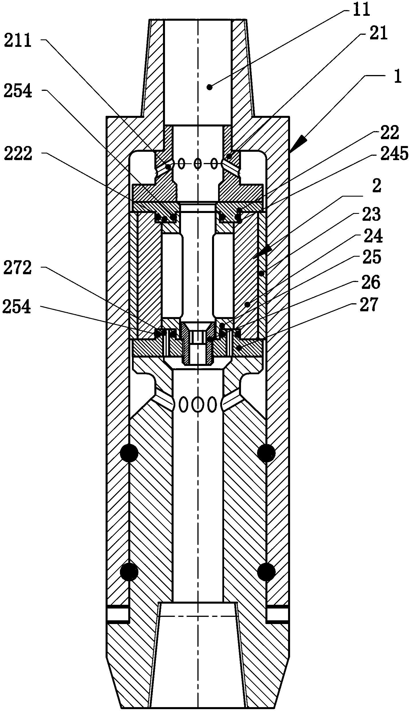
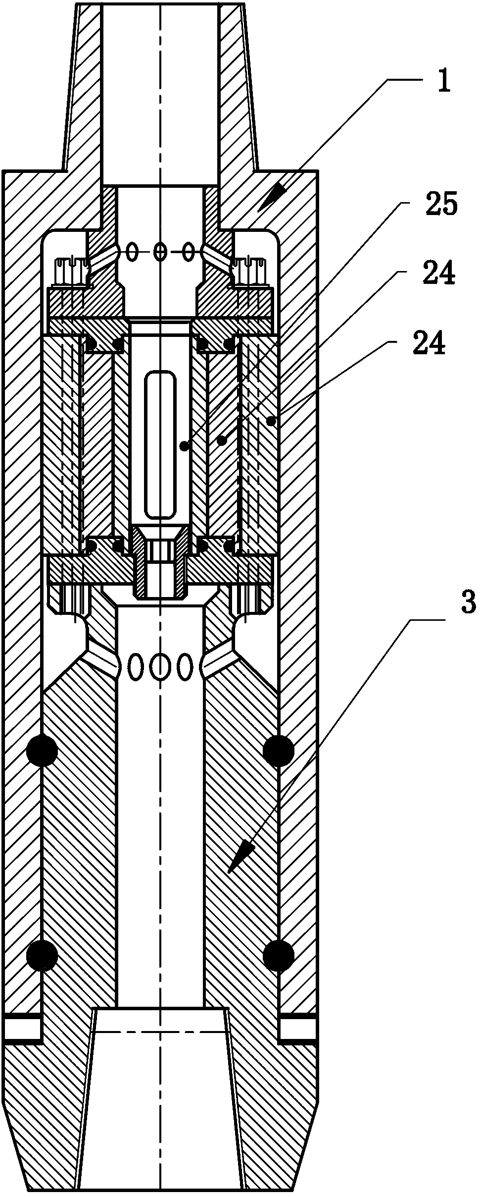
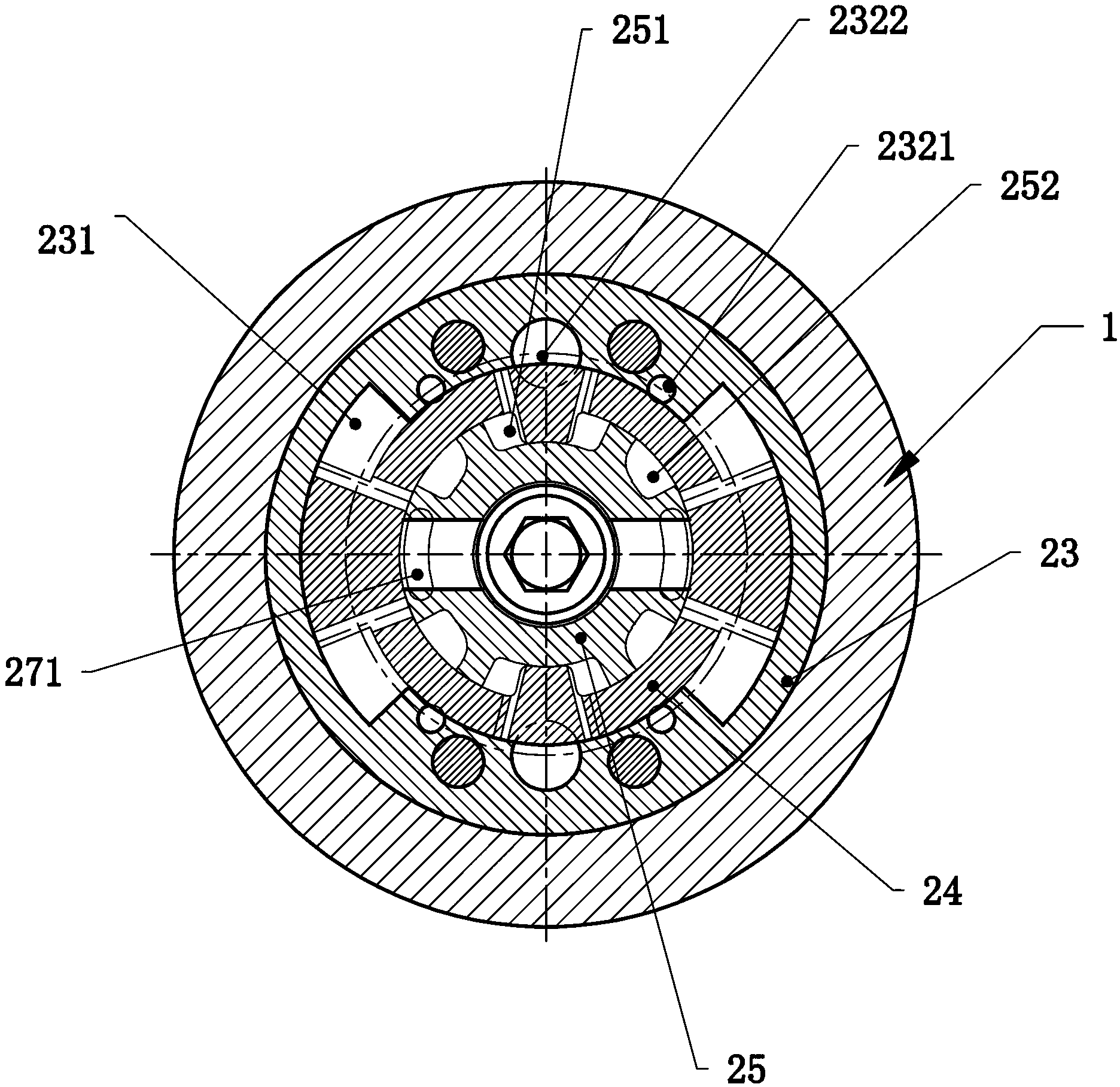
[0022] Such as figure 1 —— Figure 12 As shown, a hydraulic torsional impact device for drilling includes a drill jack sub 1, a hydraulic torsional impact generator 2 and a drill bit mount 3. The hydraulic torsional impact generator 2 is placed in the drill jack sub 1. In the embodiment of the present invention, the hydraulic torsional impact generator 2 is mainly composed of a diversion positioning cover 21, an upper rotary gland 22, an impact hammer 24, an impact hammer seat 23, a steering diverter 25, a shut-off nozzle 26, a lower The rotary gland 27 is composed of a diversion positioning cover 21, an upper rotary gland 22, an impact hammer seat 23 and a lower rotary gland 27 are fastened to the drill bit mounting seat 3 by bolts, and the impact hammer 24, impact hammer Both the shaft centers of the hammer seat 23 and the steering splitter 25 are set through holes, wherein the steering splitter 25 is sleeved on the shaft center through hole of the impact hammer 24, and the...


PUM


Abstract

The invention relates to a water pressure torsional impact device for drilling engineering. The water pressure torsional impact device adopts the technical scheme that the water pressure torsional impact device for the well drilling is characterized in that a water pressure torsional impact generator mainly comprises a flow guide location cover, an upper rotating gland, an impact rammer, an impact rammer seat, a steering divider, a cutoff nozzle and a lower rotating gland, wherein the flow guide location cover, the upper rotating gland, the impact rammer seat and the lower rotating gland are fastened with a drilling bit mounting seat by bolts; through holes are formed in axes of the impact rammer, the impact rammer seat and the steering divider; the through hole in the axis of the impact rammer is sleeved with the steering divider; the impact rammer is arranged on the through hole in the axis of the impact rammer seat; with the adoption of the scheme, the water pressure torsional impact device overcomes defects in the prior art, and a downhole tool capable of increasing the rate of penetration in a harder or abrasive stratum and avoiding stick-slip of a PDC (polycrystalline diamond compact) drilling bit is provided.

Description

technical field [0001] The invention relates to a hydraulic torsional impact device used in drilling engineering. Background technique [0002] The existing drill bits have the following problems in the use process: (1) During the drilling process, the drill bit usually has sticking, slipping, and drill sticking phenomena, and the drill string is always tightened like a clockwork, and it is released quickly after the torque is accumulated. , This kind of engineering problem is relatively serious, the torsional vibration of the drill string makes the whole drilling process unstable, and has an adverse effect on the service life of the drill bit and the supporting parts of the drill string. (2) For hard formations or abrasive formations, the penetration depth of the drill bit is not enough, and the ROP needs to be improved. [0003] At present, all kinds of rotary punching or punching rotary tools used in drilling operations can only produce axial impact force, not only will ...

Claims


Application Information

Patent Timeline
Patent Type & Authority Applications(China)
IPC IPC(8): E21B4/14
Inventor 刘升旗周加银高光亮李永安安庆宝林继兴李勇李佳临
Owner WENZHOU JIADA MACHINERY MFG
Learn More