Oil tank for leak test
A technology of fuel tank and tank body, which is applied in the direction of fuel supply tank device, pipeline support, pipe/pipe joint/pipe fitting, etc., can solve problems such as inconvenience and manual fixing of air pipe, and achieve the effect of ensuring load-bearing strength, improving efficiency and saving manpower
- Summary
- Abstract
- Description
- Claims
- Application Information
AI Technical Summary
Problems solved by technology
Method used
Image
Examples
Embodiment 1
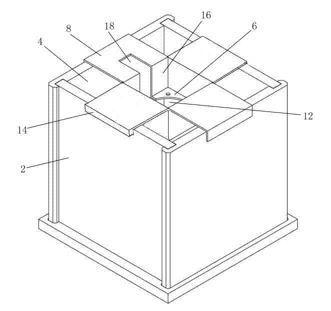
[0017] Such as figure 1 As shown, an oil tank for gas leakage inspection includes a square hollow box 2 with an open upper end, and the box 2 has a cavity 4 for containing liquid. The fuel tank also includes a trachea fixing frame that can be erected on the upper end of the tank 2. The tracheal fixing frame includes a plate-shaped body 6 and four supporting plates 8 evenly arranged in the circumferential direction of the body 6 and extending laterally outward. The middle of the body 6 is provided with a trachea fixing hole 12, and the free end of the support plate 8 is vertically provided with a flange 14; when the trachea fixing frame is erected on the upper end of the box 2, the flange 14 of each support plate 8 is close to the side of the box 2. wall.
[0018] When installing the trachea fixing frame, make the four supporting plates 8 perpendicular to the four sides of the box 2 and put them on the upper end of the box 2, and the flange 14 extends downwards relative to the su...
Embodiment 2
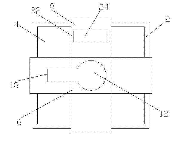
[0022] Such as Figure 1-2 As shown, an oil tank for air leakage inspection is different from Embodiment 1 in that a block support seat 22 is vertically provided on a support plate 8 and a groove is provided at the top of the support seat 22. The bottom surface 24 of the groove is an arc-shaped curved surface that is vertically recessed toward the surface of the supporting plate 8. The axial direction of the curved surface is perpendicular to the axial direction of the tracheal fixing hole 12 and parallel to the extending direction of the supporting plate 8. The rear end of the trachea inserted into the trachea fixing hole 12 can be erected in the groove of the support base 22 to prevent the trachea from swaying left and right under the influence of the airflow, agitating the oil and affecting the inspection result. The arc-shaped surface fits more closely to the shape of the circular trachea, increasing stability.
Embodiment 3
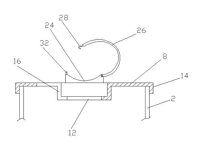
[0024] Such as figure 1 , 3 As shown, an oil tank for air leakage inspection is different from Embodiment 2 in that: the support base 22 is provided with a hook 26 that can cooperate with the groove to form a closed loop, and one end of the hook 26 is axially connected to the support base 22 , The other end is provided with a fixed hook 28, which can be movably connected with a fixed ring 32 provided on the support base 22. When in use, first open the hook 26 relative to the groove, set up the trachea in the groove, and extend into the fixing hole, then close the hook 26 relative to the groove, and connect the fixing hook 28 with the fixing ring 32 to firmly Lock the position of the trachea firmly and prevent the trachea from jumping up and down.
PUM
 Abstract
Description
Claims
Application Information
 - R&D
- Intellectual Property
- Life Sciences
- Materials
- Tech Scout
- Unparalleled Data Quality
- Higher Quality Content
- 60% Fewer Hallucinations
Browse by: Latest US Patents, China's latest patents, Technical Efficacy Thesaurus, Application Domain, Technology Topic, Popular Technical Reports.
© 2025 PatSnap. All rights reserved.Legal|Privacy policy|Modern Slavery Act Transparency Statement|Sitemap|About US| Contact US: help@patsnap.com


