
Method and device for preventing irrigation electronic control valve from being out of operation

A technology of working failure and electric control valve, which is applied in the direction of valve operation/release device, valve device, valve details, etc., can solve the problems of small control channel aperture, poor reliability, incomplete emptying of water, etc., and achieve fast switching control Agility, improve work reliability and work stability, improve the effect of water inlet and discharge speed

Inactive Publication Date: 2013-09-11
遵义群建塑胶制品有限公司
View PDF7 Cites 1 Cited by
  • Summary
  • Abstract
  • Description
  • Claims
  • Application Information

AI Technical Summary

Problems solved by technology

In actual application, due to the small pore size of the control channel, it is often blocked by sediment or impurities in the water
In addition, when the current electric control valve for irrigation is working, the water in the valve cavity is not completely emptied, and a large amount of sediment or impurities will be deposited, which will cause the work of the electric control valve to fail.
Therefore, the working state of the existing irrigation electronic control valve is extremely unstable, the reliability is poor, and frequent maintenance is required, which also increases the workload and maintenance cost of daily maintenance.

Method used


Image

  • Method and device for preventing irrigation electronic control valve from being out of operation
  • Method and device for preventing irrigation electronic control valve from being out of operation

Examples


Embodiment Construction

[0015] The present invention will be further described in detail below in conjunction with the accompanying drawings, but not as any limitation to the present invention.

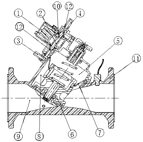
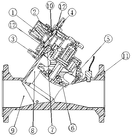
[0016] A method to prevent the failure of the electric control valve for irrigation, such as figure 1 and figure 2 shown. In this method, the water passage 9 in the electric control valve is isolated from the upper cavity 5 through the elastic cup 7 arranged between the valve core assembly 6 and the valve cavity, and the upper cavity 5 is connected to the control channel; at the same time, the pilot diaphragm 12. Isolate the entire control mechanism from the waterway to prevent the impact of sediment and impurities on the movement of the control mechanism; to improve the reliability of the electric control valve. The control channel adopts a larger aperture of 6-8mm to reduce the blockage of the control channel by silt or impurities; at the same time, the silt or impurity deposition in the cavity is reduc...


PUM


Abstract

The invention discloses a method and device for preventing an irrigation electronic control valve from being out of operation. A water channel in a magnetic valve is isolated from an upper cavity body through an elastic packing cup which is placed between a valve element assembly and a valve cavity, the upper cavity body is connected with a control channel, and meanwhile a whole control mechanism is isolated from a water route through a pre-guiding film sheet to prevent sediment and other sundries from affecting the operation of the control mechanism and to improve the work reliability of the electronic control valve. Due to the fact that the pre-guiding film sheet is used for isolating the whole control mechanism from water, the sediment and other sundries can be prevented from affecting the normal work of the control mechanism. The bore diameter of an outer circulation channel is enlarged, so that the water containing the sediment and the sundries flows successfully, the process that the water flows in and out of the valve cavity is accelerated, and a switch of the electronic control valve is controlled fast and flexibly. The water inlet process and the water outlet process of the upper cavity body are respectively controlled through a double-direction micromotor, in each water draining process, the water inside the valve cavity can be drained thoroughly, the sediment and the sundries in the upper cavity body are brought away, the phenomenon that a large amount of sediment is deposited inside the valve cavity is avoided, and the working reliability and the working stability of the electronic control valve are improved.

Description

technical field [0001] The invention relates to a method and a device for preventing work failure of an electric control valve for irrigation, and belongs to the technical field of improving the work reliability of the electric control valve. Background technique [0002] The control channels of the existing electric control valves for irrigation all use internal channels, and due to the limitation of structure and function, smaller apertures are used, generally 1.5mm-2.5mm. In practical application, due to the small pore size of the control channel, it is often blocked by sediment or impurities in the water. In addition, when the current electric control valve for irrigation works, the water in the valve cavity is not completely emptied, and a large amount of silt or impurities will be deposited to cause the work of the electric control valve to fail. Therefore, the working state of the existing electric control valve for irrigation is extremely unstable, the reliability i...

Claims


Application Information

Patent Timeline
Patent Type & Authority Applications(China)
IPC IPC(8): F16K31/126
Inventor 陈勇陈良富吴世海宋大海卢永华
Owner 遵义群建塑胶制品有限公司
Learn More