Multi-shaft support air floatation platform leveling method
An air-floating platform and shaft support technology, which is applied in the directions of supporting machines, machine tables/brackets, and feedback control, etc., and can solve the problems of narrow application scope and limited leveling state of supporting platforms.
- Summary
- Abstract
- Description
- Claims
- Application Information
AI Technical Summary
Problems solved by technology
Method used
Image
Examples
specific Embodiment approach 1
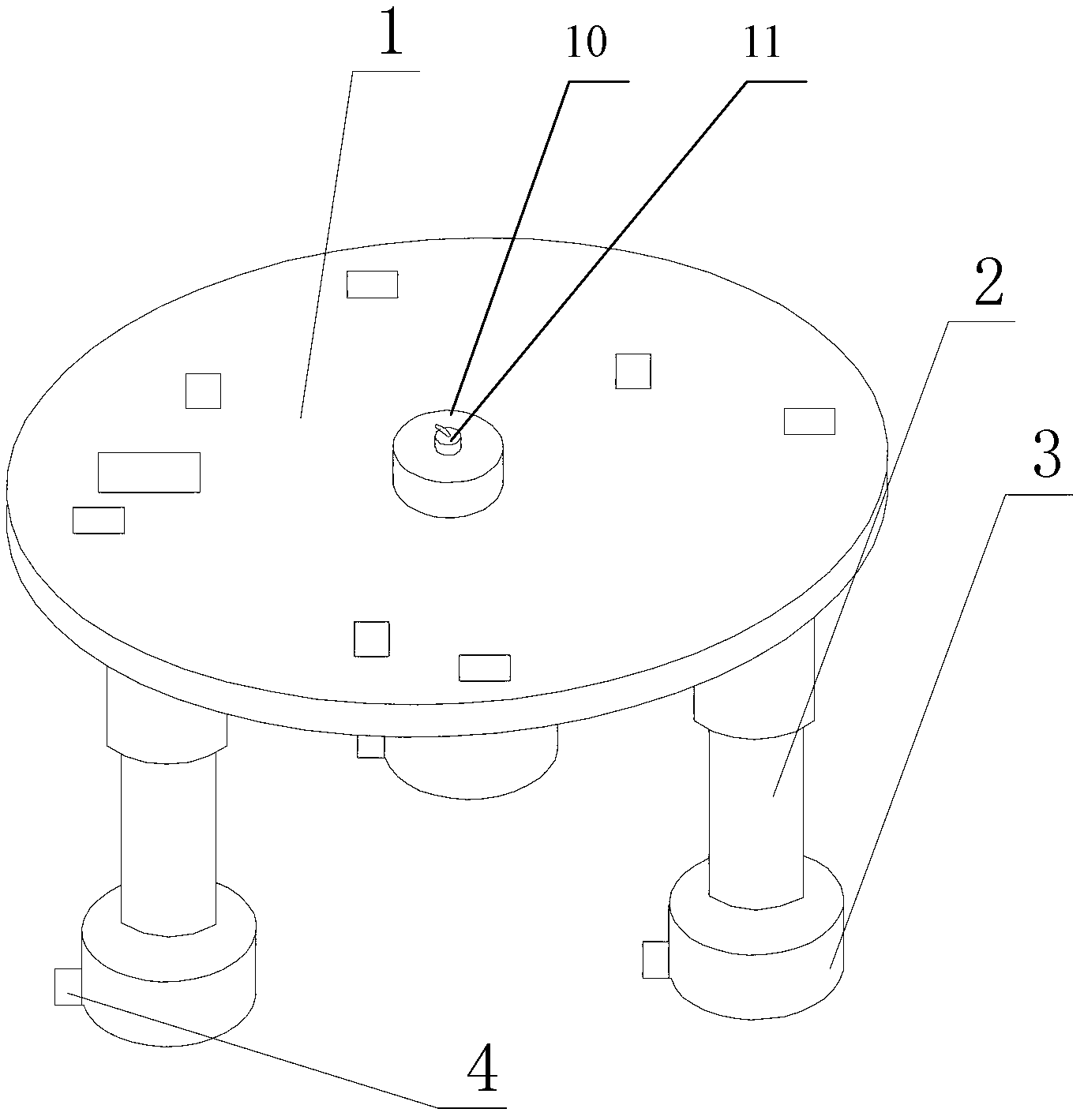
[0071] Specific implementation mode 1: the following combination Figure 1 to Figure 10 In this embodiment, the leveling method of the multi-axis support air floating platform in this embodiment will be described. The multi-axis support air floating platform includes a bearing platform 1, M supporting legs 2, M air floats 3, and M air feet. 4, M is 3, 4, 5, 6, 7 or 8,
[0072] The carrying platform 1 is a circular platform, the carrying platform 1 is supported by M supporting legs 2, and M connecting points between the M supporting legs 2 and the lower surface of the carrying platform 1 form a regular M polygon;
[0073] The end of each support leg 2 is connected with an air float 3, and the bottom end of each air float 3 is connected with an air foot 4 through an air float ball bearing;
[0074] The leveling method realizes leveling through a measurement control system of a multi-axis supporting air-floating platform. The measurement control system includes a load feedback unit 5, a...
specific Embodiment approach 2
[0101] Specific implementation manner 2: the following combination Picture 8 This embodiment will be described. This embodiment will further explain the first embodiment. In this embodiment, M is 3, and the controller 9 in step 6 and step 7 performs data fusion processing on all the feedback signals it reads to obtain The specific method of adjusting the amount of support leg 2 is:
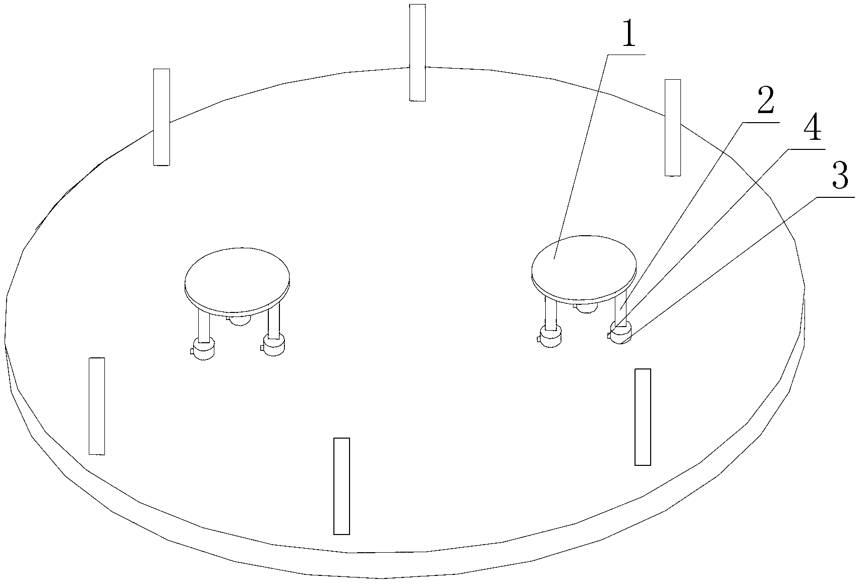
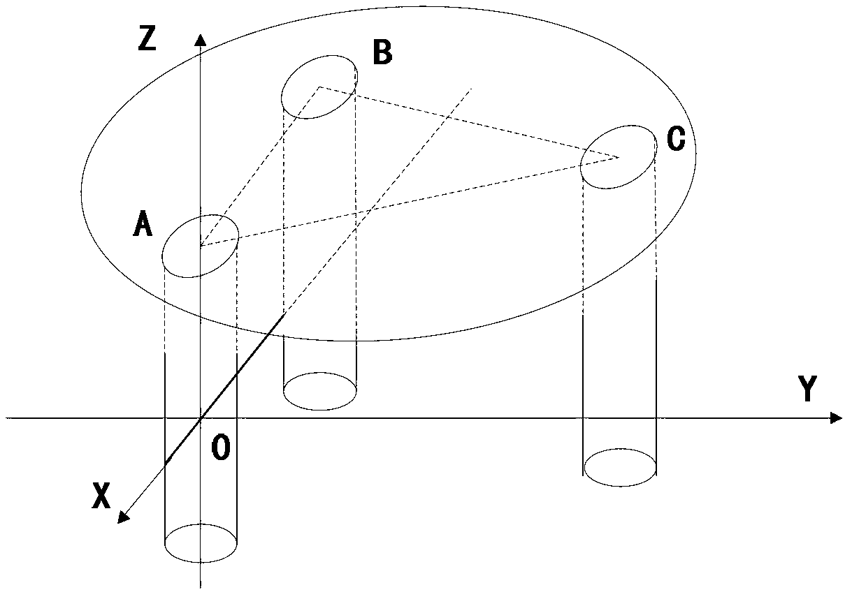
[0102] Set the linear array CCD7-3 to consist of six CCDs. The six CCDs on the circular horizontal concrete base are numbered in the circumferential direction as ①, ②, ③, ④, ⑤ and ⑥, with No. ④ CCD and No. ① The center line of the CCD is used as the X-axis direction of the spatial rectangular coordinate system, which is located on the horizontal plane X-0-Y where the reference light of the linear light source 11 is located, and the Y-axis of the spatial rectangular coordinate system is defined according to the right-hand rule Direction and Z-axis direction, set the radius of the circular horizontal ...
specific Embodiment approach 3
[0122] Specific implementation manner 3: the following combination Figure 1 to Figure 10 This embodiment will be described. This embodiment will further explain the first or second embodiment. The radius of the carrying platform 1 in this embodiment is 2 meters, and the three supporting legs are equilateral formed by three connection points on the lower surface of the carrying platform 1 The distance between the vertex of the triangle and the center of the bearing platform 1 is 1.4 meters.
[0123] image 3 As shown, the support leg 2 of the multi-axis supporting air bearing platform and the three connection points A, B, and C on the lower surface of the bearing platform 1 form an equilateral triangle with a side length of L=2424 mm. The air foot 4 relies on compressed air to form an air film between the air float ball bearing and the ball sleeve to achieve a nearly frictionless motion to simulate the dynamic environment of the spacecraft in the outer space with extremely small d...
PUM
 Abstract
Description
Claims
Application Information
 - R&D
- Intellectual Property
- Life Sciences
- Materials
- Tech Scout
- Unparalleled Data Quality
- Higher Quality Content
- 60% Fewer Hallucinations
Browse by: Latest US Patents, China's latest patents, Technical Efficacy Thesaurus, Application Domain, Technology Topic, Popular Technical Reports.
© 2025 PatSnap. All rights reserved.Legal|Privacy policy|Modern Slavery Act Transparency Statement|Sitemap|About US| Contact US: help@patsnap.com


