
Wind stopping device of cooling tower of thermal power plant

A technology for cooling towers and thermal power plants is applied in the field of new structures of cooling tower windshield devices in thermal power plants, which can solve the problems of increased height of cooling towers, damage to windshields, and inability to effectively prevent ice from hanging on cooling towers, and achieves reduced deformation. Effect

Inactive Publication Date: 2013-09-11
HARBIN INST OF TECH
View PDF5 Cites 4 Cited by
  • Summary
  • Abstract
  • Description
  • Claims
  • Application Information

AI Technical Summary

Problems solved by technology

However, with the rapid development of the electric power industry, large-scale generator sets have been put into operation one after another, and the capacity of a single unit has continued to increase. The water spraying area of ​​the cooling tower has also increased accordingly, resulting in an increase in the height of the air inlet of the cooling tower, resulting in the suspension of this windshield. The board has a large area and heavy weight, and it takes a lot of manpower and material resources to hang and remove the windshield
Moreover, this kind of windshield is seriously damaged during use, it is difficult to ensure the tightness of the windshield device, and it cannot effectively prevent the ice hanging phenomenon of the cooling tower in winter

Method used


Image

  • Wind stopping device of cooling tower of thermal power plant
  • Wind stopping device of cooling tower of thermal power plant
  • Wind stopping device of cooling tower of thermal power plant

Examples


Embodiment Construction

[0028] The specific embodiment of the present invention will be further described below in conjunction with accompanying drawing:

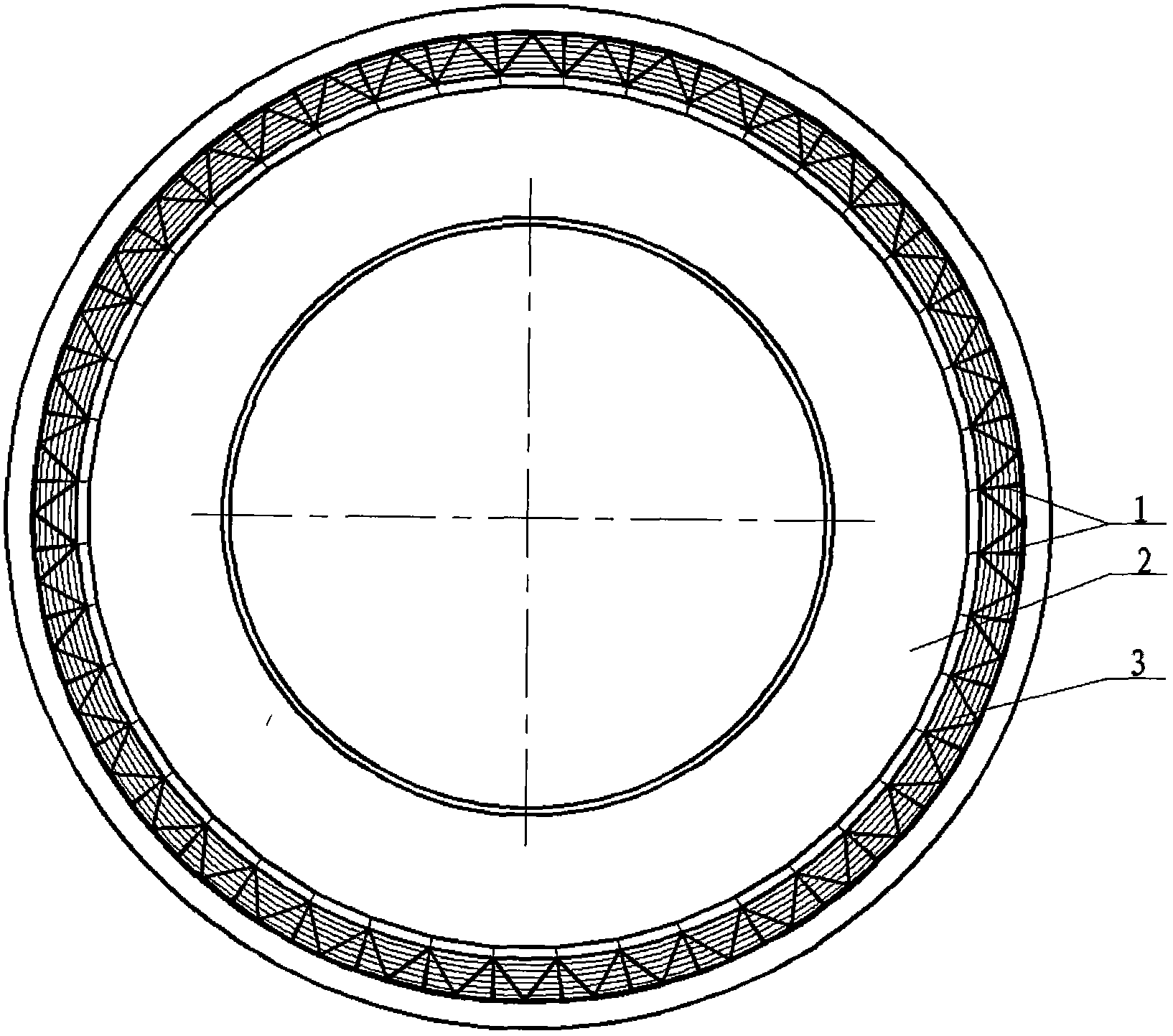
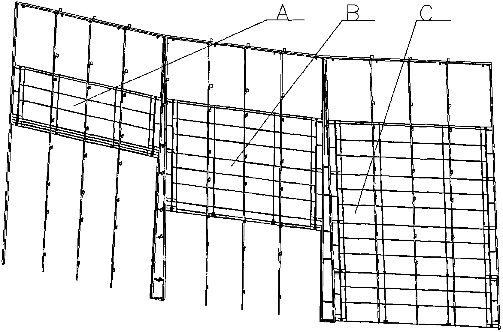
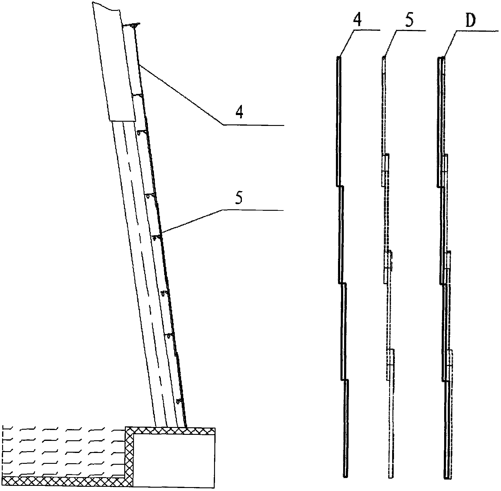
[0029] like figure 1 As shown, because the area of ​​the cooling tower 2 is very large, the wind shielding device of the cooling tower designed in the present invention adopts the idea of ​​modular design, and the wind shielding device of the cooling tower is designed as independent wind shielding device units one by one, each wind shielding The wind device unit passes through the original ring-shaped steel pipe 3 and C-shaped steel guide rail 1 fixed on the cooling tower and image 3 The shown rear bracket 4 is connected to the cooling tower, and each windshield device unit is connected as a whole through the connecting steel plate between the adjacent C-shaped steel guide rails 1 and the upper bracket, so that the cooling tower windshield can be tightly "wrapped "Live the cooling tower.

[0030] figure 2 It is the overall schematic diagram o...


PUM


Abstract

The invention provides a novel-structure wind stopping device of a cooling tower of a thermal power plant. The structure of the wind stopping device is of an overlapped type; and the structure can effectively reduce the space occupied by the wind stopping device and the size of an air inlet can be conveniently adjusted according to the change of an outer environment of the cooling tower, so that the air inlet quantity of the cooling tower is changed, and the normal operation of the cooling tower is guaranteed. The wind stopping device is composed of overlapped wind stopping plates, a wind stopping plate supporting device and a steel wire rope power transmission device. The overlapped wind stopping plates are connected into a whole body through a guide rail; the wind stopping device can slide in a supporting structure through using a steel wire rope to transmit power, so that the wind stopping device can properly adjust the size of the air inlet of the cooling tower according to the change of the outer environment to take the wind stopping and anti-freezing effects and guarantee the normal operation of the cooling tower in different seasons.

Description

technical field [0001] The invention relates to a wind-shielding device, in particular to a novel structure of a wind-shielding device for a cooling tower of a thermal power plant. Background technique [0002] Due to the harsh winter weather conditions in Northeast my country and North China, cooling towers operating in winter will have varying degrees of icing. After the freezing phenomenon occurs at the air inlet of the cooling tower, the air inlet area of ​​the air inlet will be reduced, resulting in a decrease in the air inlet of the cooling tower, which will affect the cooling effect of the cooling tower. The freezing of the filler in the cooling tower will reduce the efficiency of the filler, and after the filler freezes, it will damage part of the filler and affect the cooling effect of the cooling tower. The occurrence of freezing will increase the structural load, and even cause damage to the concrete structure of the tower, reducing the service life of the struct...

Claims


Application Information

Patent Timeline
IPC IPC(8): F28C1/16
Inventor 周亮李亮张海兵
Owner HARBIN INST OF TECH
Learn More