Imaging device and imaging method

A technology of camera device and camera department, which is applied in the direction of image communication, TV, color TV parts, etc., and can solve the problems of darkening of dynamic images and inability to ensure exposure time, etc.

Inactive Publication Date: 2013-09-11
CASIO COMPUTER CO LTD
View PDF5 Cites 9 Cited by
  • Summary
  • Abstract
  • Description
  • Claims
  • Application Information

AI Technical Summary

Problems solved by technology

[0007] Therefore, there is a problem that an appropriate exposure time cannot be ensured accordi

Method used


Image

  • Imaging device and imaging method
  • Imaging device and imaging method
  • Imaging device and imaging method

Examples


Embodiment Construction

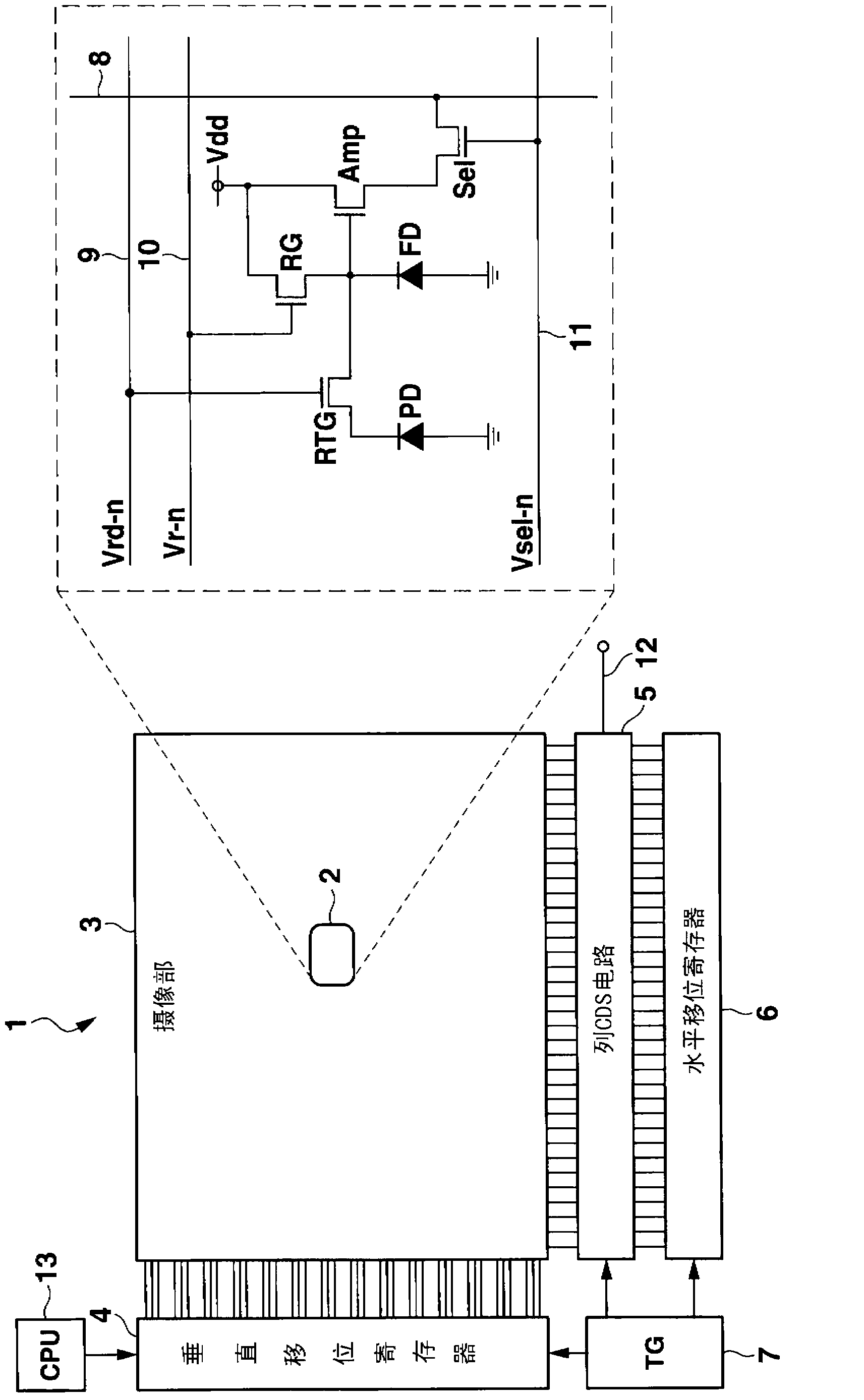
[0018] Embodiments of the present invention will be described below. figure 1 It is a schematic configuration diagram showing the CMOS image sensor 1 according to the present invention.

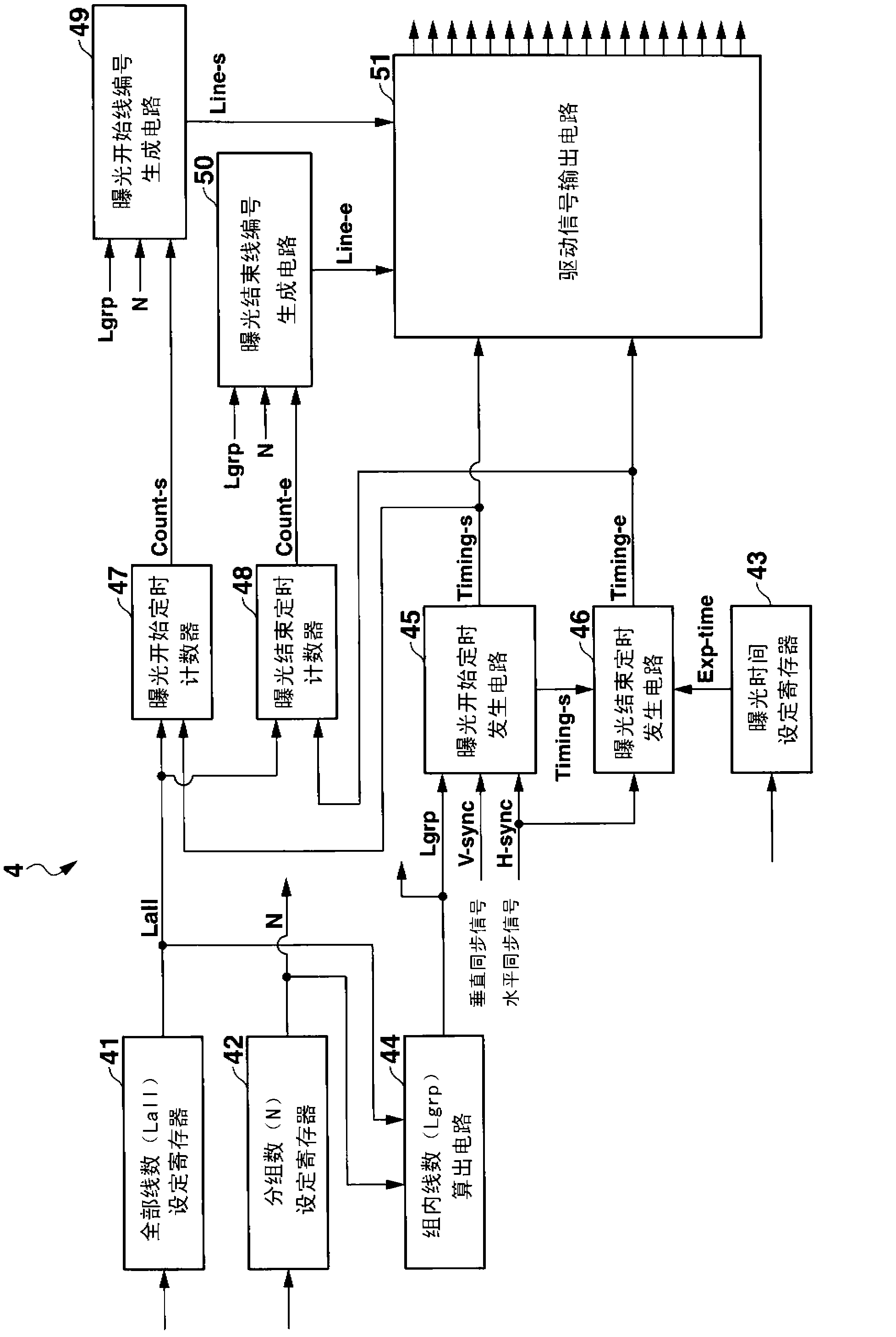
[0019] The CMOS image sensor 1 is configured as follows, and has an imaging unit 3 in which a plurality of pixels 2 are two-dimensionally arranged in the vertical direction and the horizontal direction, a vertical shift register 4 as a driving mechanism, a column CDS (Correlated Double Sampling) circuit 5, Horizontal shift register 6, TG (Timing Generator) 7, etc. In the imaging unit 3 , vertical signal lines 8 are wired for each column, and transfer signal lines 9 , reset signal lines 10 , and selection signal lines 11 are wired for each row to each pixel 2 .

[0020] and, if figure 1 As shown, each pixel 2 is composed of a photodiode PD, a transfer transistor RGT, an amplifier transistor Amp, a pixel selection transistor Sel, a reset transistor RG, and a floating diffusion FD.

[0021]...


PUM


Abstract

An imaging device, an imaging method and a nonvolatile recording medium are provided. The imaging device includes an imaging unit having a pixel group two-dimensionally arranged vertically and horizontally, and configured to read pixel signals associated with generation of a frame image in units of lines by a rolling shutter system, and a drive unit configured to periodically switch, when a plurality of frame images are consecutively read from the imaging unit with a predetermined frame period in video recording, positions of a plurality of lines each of which is made a read object in each of the frame images in units of frames.

Description

technical field [0001] The present invention relates to an imaging device and an imaging method using a rolling shutter method. Background technique [0002] In recent years, digital cameras and video cameras employing a CMOS (Complementary Metal Oxide Semiconductor) type imaging device (hereinafter referred to as a CMOS image sensor) have generally spread. The CMOS image sensor is a structure in which a signal of each pixel is output by X-scan (vertical scan) and Y-scan (horizontal scan) from pixel groups arranged two-dimensionally in the vertical and horizontal directions. [0003] As a method of driving a CMOS image sensor, for example, a rolling shutter method described in Patent Document 1 (Japanese Patent Application Laid-Open No. 2008-288904 ) described below is relatively common. The rolling shutter method is a method of sequentially scanning pixel groups arranged two-dimensionally in the vertical direction and the horizontal direction for each line in one frame per...

Claims


Application Information

Patent Timeline
IPC IPC(8): H04N5/232H04N5/235
CPCH04N25/531H04N25/76H04N25/00
Inventor 铃木宗士
Owner CASIO COMPUTER CO LTD
Why Eureka
Try Eureka