
Time Division Wavelength Multiplexing Passive Optical Network

A passive optical network and wave multiplexing technology, applied in the field of passive optical network, can solve the problem of tight bandwidth allocation and achieve the effect of low cost, expanded transmission capacity and low cost

Inactive Publication Date: 2016-02-17
李三良
View PDF2 Cites 0 Cited by
  • Summary
  • Abstract
  • Description
  • Claims
  • Application Information

AI Technical Summary

Problems solved by technology

For example, in a WDM-PON supplying 32 ONUs, assuming that the channel width is 0.8nm, in addition to the bandwidth of 51.2nm required for uplink and downlink transmission, channel monitoring also requires an additional 25.6nm optical bandwidth, if It also has other channel services, such as video, voice and Radioover Fiber (Rof) to join the WDM-PON architecture, then bandwidth allocation will become very tight

Method used


Image

  • Time Division Wavelength Multiplexing Passive Optical Network
  • Time Division Wavelength Multiplexing Passive Optical Network
  • Time Division Wavelength Multiplexing Passive Optical Network

Examples


Embodiment Construction

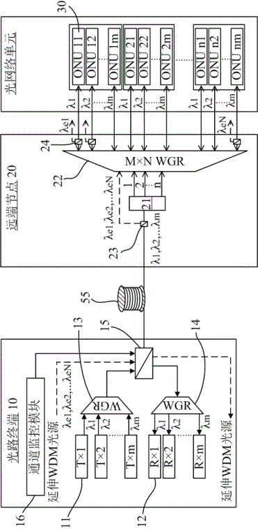
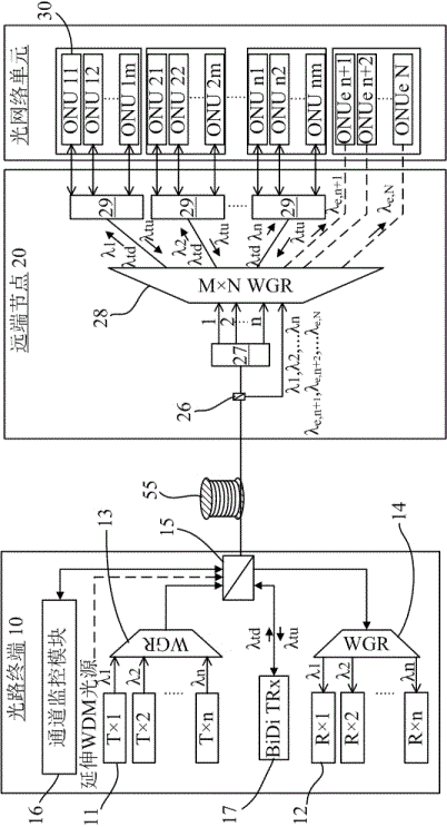
[0023] figure 1 A schematic diagram showing the architecture of a TWDM passive optical network (TW-PON) according to the first embodiment of the present invention. The time-division multiplexing passive optical network according to the first embodiment of the present invention is a time-division-based wavelength-division passive optical network, or called a wave-division-like passive optical network (WDM-PONlike), Such as figure 1 As shown, its structure can be divided into an optical terminal 10 (such as located in the central office of a service provider), a remote node 20 and several optical network units 30, and optical signals are transmitted by wiring fibers 55 therebetween.

[0024] Such as figure 1 As shown, a 1×n optical splitter (Optical Splitter) 21 and an M×N MIMO waveguide grating router (WGR) 22 are arranged at the remote node 20 . The optical splitter 21 will receive a group of mixed optical signals {λ 1 ,λ 2 ,...λ m}, and split the mixed optical signal to...


PUM


Abstract

The invention discloses a TWPON, an optical splitter (21) and a WGR (22) are arranged on a RN (20), the optical splitter (21) and the WGR (22) can be in cascade connection or parallel connection to be implemented, and therefore the purpose of promoting transmission capacity or increasing user quantities can be realized by means of smaller wavelength; the invention further provides a platform where a time-division multiplexed passive optical network, a wavelength-division multiplexed passive optical network and a hybrid passive optical network exist simultaneously, and a channel barrier monitoring mechanism of the smaller wavelength.

Description

technical field [0001] The present invention is related to a passive optical network (Passive Optical Network, PON), in particular to a passive optical network capable of elastically increasing transmission capacity and expanding the number of users. Background technique [0002] A passive optical fiber network generally includes an optical line terminal (OpticalLineTermination, OLT), a remote node (RemoteNode, RN) and several optical network units (OpticalNetworkUnits, ONUs). The terminal device (such as a computer) is connected to the ONU, and the ONU will convert the signal from the terminal device into an optical signal, and then transmit it to the service provider's central office (CentralOffice, CO) through the optical fiber through the RN's optical split, which is the aforementioned The OLT. After the OLT performs various signal processing, the communication between the ONU and another ONU, or the communication between the ONU and another terminal on the network can ...

Claims


Application Information

Patent Timeline
Patent Type & Authority Patents(China)
IPC IPC(8): H04Q11/00
Inventor 李三良
Owner 李三良
Learn More