High-precision rotary device

A rotating device and high-precision technology, which is applied in the direction of removing conductive materials by chemical/electrolytic methods, can solve the problems of high cost, positioning accuracy of rotating device, and repeated positioning accuracy that cannot meet the requirements of laser imaging devices, etc., and achieve low cost , simple structure, and extensive use of value

Active Publication Date: 2013-09-11
HANS CNC SCI & TECH
View PDF2 Cites 7 Cited by
  • Summary
  • Abstract
  • Description
  • Claims
  • Application Information

AI Technical Summary

Problems solved by technology

[0003] The purpose of the present invention is to solve the shortcomings of high-precision rotating devices in existing laser direct imaging devices, and the positioning accuracy and repeat positioning accuracy of some rotating devices cannot meet the requirements of laser imaging devices, and provide a high-precision rotating device

Method used


Image

  • High-precision rotary device
  • High-precision rotary device

Examples


Embodiment Construction

[0019] In order to make the object, technical solution and advantages of the present invention clearer, the present invention will be further described in detail below in conjunction with the accompanying drawings and embodiments. It should be understood that the specific embodiments described here are only used to explain the present invention, not to limit the present invention.

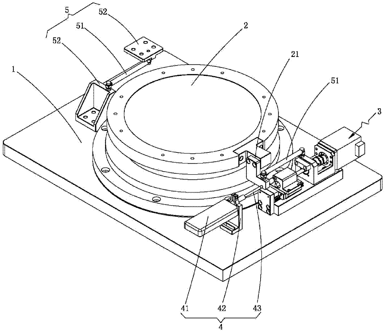
[0020] see figure 1 , the present invention provides a high-precision rotating device, including an installation base plate 1 and a rotating panel (not shown in the figure), and also includes a The air-floating rotary bearing 2, the driving device 3 for driving the air-floating rotary bearing 2 to rotate, and the length meter 41 for measuring the linear displacement of the driving device 3, the air-floating rotary bearing 2 is provided with a connecting piece 21. The present invention is applied in the field of laser direct imaging processing, and is placed under the vacuum platform of laser direc...


PUM


Abstract

The invention provides a high-precision rotary device which comprises an installing base plate and a rotary panel. The high-precision rotary device is characterized by further comprising an air floatation rotary bearing arranged between the installing base plate and the rotary panel, a driving device used for driving the air floatation rotary bearing to rotate, and a length gauge used for measuring the linear displacement of the driving device, and the air floatation rotary bearing is provided with a connecting piece. The locating precision of the high-precision rotary device is less than or equal to 5'', the repeated locating precision of the high-precision rotary device is less than or equal to 2.5'', and the rotating angle of the high-precision rotary device is + / -5 degrees. The high-precision rotary device is applied to the field of laser direct imaging processing, and is simple in structure, small in number of parts and convenient to install. Due to the fact that a low-power stepping motor and the length gauge, instead of a high-precision circular-arc optical grating ruler, are adopted to carry out repeated measurement, to carry out feedback and to determine the repeated locating precision, the high-precision rotary device is low in cost and applicable to practical application, and has wide industrial use value.

Description

technical field [0001] The invention relates to the field of PCB laser direct imaging processing, in particular to a high-precision rotating device. Background technique [0002] Laser direct imaging is a technology that directly uses the data output by the CAM workstation to drive the laser imaging device and perform imaging on the printed circuit board coated with photoresist. Because of its quick response capability and low production cost, this technology is gradually being widely used in PCB board printing. During the processing of the laser imaging device, since two right-angled sides are used for initial positioning when the PCB is loaded, the actual position of the PCB will be caused by the deviation between the two right-angled sides and the target point of the PCB or the deviation of the material. There is a certain error with the reference position, and because the laser direct imaging equipment has high imaging accuracy, the error value is required to be small, ...

Claims


Application Information

Patent Timeline
Patent Type & Authority Applications(China)
IPC IPC(8): H05K3/06
Inventor 李红宇巢宏斌胡湘衡高云峰
Owner HANS CNC SCI & TECH
Why Eureka
Try Eureka