Groove type self-balancing eccentric shaft

A self-balancing, eccentric shaft technology, applied in the direction of eccentric shafts, shafts, shafts, and bearings, can solve the problems of increased power consumption, increased manufacturing costs, and operational power consumption, as well as the complexity of the jaw crusher mechanism, so as to reduce equipment manufacturing and Operating costs, increased material and processing costs, and the effect of eliminating double power consumption factors

Inactive Publication Date: 2013-09-18
YIWU BLACK AND WHITE MINING MACHINERY
View PDF13 Cites 0 Cited by
  • Summary
  • Abstract
  • Description
  • Claims
  • Application Information

AI Technical Summary

Problems solved by technology

[0005] The method of solving eccentric vibration in the above-mentioned prior art has the following deficiencies: ① It is necessary to add a pair of heavy flywheels and add eccentric balance weights on the flywheels, which complicates the mechanism of the jaw crusher and increases the manufacturing cost and power consumption in operation; In equipment manufacturing, it is difficult to detect the accuracy of its moment of inertia balance (the weight of the eccentric block is insufficient or exceeds,...

Method used


Image

  • Groove type self-balancing eccentric shaft
  • Groove type self-balancing eccentric shaft
  • Groove type self-balancing eccentric shaft

Examples


Embodiment 1

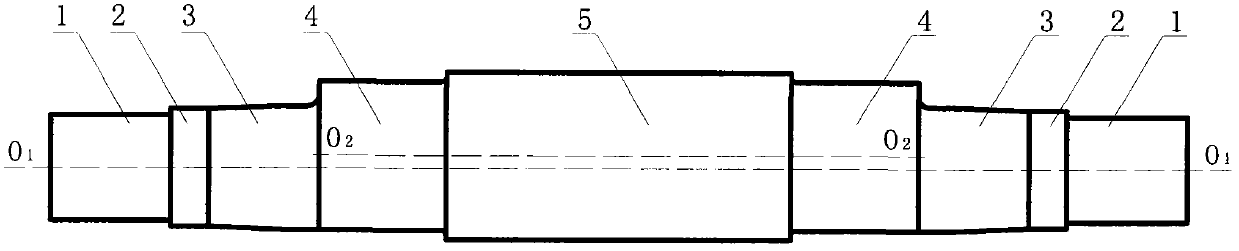
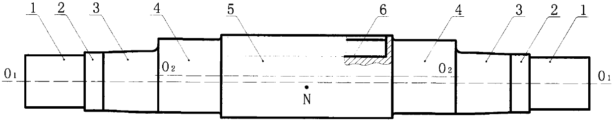
[0037] Embodiment 1: as figure 2 As shown, a grooved self-balancing eccentric shaft is composed of an eccentric bearing gear 4, a concentric bearing gear 3, a locking gear 2 and a reference gear 1 that are symmetrically connected on both sides of the connecting gear 5 from the inside to the outside. The axes of concentric bearing gear 3, locking gear 2 and reference gear 1 on the side are located on the rotation center line O of the whole shaft 1 -O 1 On the top, the center of the eccentric bearing gear 4 on both sides is located on the eccentric centerline O of the whole shaft 2 -O 2 superior;

[0038]A groove 6 is arranged on the connecting gear 5 relative to the eccentric side of the eccentric bearing gear 4, and the center line of the groove 6 is located on the plane where both the eccentric center line of the eccentric bearing gear 4 and the rotation center line of the concentric bearing gear 3 are located; The centroid point N of the connecting gear 5 is located on ...

Embodiment 2

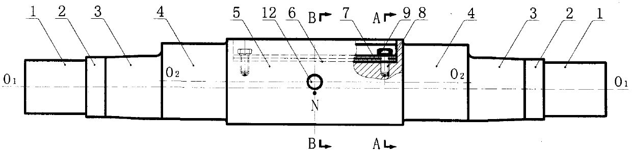
[0039] Embodiment 2: as image 3 and Figure 4 As shown, the matching overlapping piece 7 is arranged in the groove 6, and the matching overlapping piece 7 is locked by the adjusting screw hole 8 and the adjusting bolt 9, and the adjusting screw hole 8 is located on the center line of the bottom of the groove 6. All the other are with embodiment 1.

Embodiment 3

[0040] Embodiment 3: as Figure 5 As shown, the connecting gear 6 is provided with a screw hole 12 that runs through its center in the radial direction, and the screw hole direction of the screw hole 12 is perpendicular to the center line of the groove 6, and a pair of screw holes 12 are provided in the screw hole 12 to be threaded. Screws for fine torque adjustment. The pair of torque fine-tuning screws includes two adjusting screws 13 and stop screws 14 that cooperate with each other and abut together one after the other.

[0041] All the other are with embodiment 2.


PUM


Abstract

The invention discloses a groove type self-balancing eccentric shaft. Part of the mass of the same eccentric side of a connecting guard and eccentric bearing guards in an eccentric shaft in the prior art is deducted, namely that the volume of a groove is milled so that the center of mass of the connecting guard shifts toward the opposite side, relative to a rotary center line, of the eccentric bearing guards and the eccentric inertia moment generated by the connecting guard is equal to the eccentric inertia moments generated by the eccentric bearing guards but the directions are opposite, thus achieving self-balancing of the eccentric inertia spin moment of the eccentric shaft. The eccentric inertia spin moment of the eccentric shaft in the prior art is self-balanced by the interior of the eccentric shaft instead of original external flywheels, thus eccentric balance weights on the external flywheels can be omitted. The groove type self-balancing eccentric shaft has high balance precision and a simplified structure, is easy to detect and control, reduces the manufacturing cost of equipment and saves the operating cost.

Description

technical field [0001] The invention relates to the technical field of jaw crushers, in particular to a grooved self-balancing eccentric shaft. Background technique [0002] Jaw crusher, commonly known as jaw crusher, is one of the oldest and most widely used crushing equipment. The eccentric shaft is the core part of the jaw crusher equipment. The jaw plate in the jaw crushing pair is tightened and loosened when crushing materials, which comes from the eccentric design of the eccentric shaft. [0003] Prior art eccentric shafts have two centerlines (see figure 1 ): ① Rotation center line, that is, the center line where the axes of the concentric bearing gear, locking gear and reference gear are located; ② Eccentric center line, that is, the center line where the axes of the eccentric bearing gear and the connecting gear are located. The working mechanism of the eccentric shaft is: when the motor is connected with the flywheel on the reference gear through the V-belt and d...

Claims


Application Information

Patent Timeline
IPC IPC(8): F16C3/18F16C3/20B02C1/02
Inventor 朱兴良
Owner YIWU BLACK AND WHITE MINING MACHINERY
Why Eureka
Try Eureka