A new type of air conditioner dehumidifier

An air-conditioning and dehumidification technology, applied in air-conditioning systems, space heating and ventilation, space heating and ventilation details, etc., can solve the problems of large volume, low cost, and low heat exchange efficiency

Active Publication Date: 2015-10-21
无锡金龙石化冶金设备制造有限公司 +1
View PDF8 Cites 0 Cited by
  • Summary
  • Abstract
  • Description
  • Claims
  • Application Information

AI Technical Summary

Problems solved by technology

However, a single evaporative cooling air conditioner can only achieve cooling, and the existing evaporative cooling is usually isohumid cooling and adiabatic humidification, which cannot achieve dehumidification, thus greatly limiting its application range. In humid areas, it is necessary to combine evaporative cooling technology with mechanical refrigeration
[0003] In the prior art, there are large-scale air-conditioning units that combine evaporative cooling with mechanical refrigeration. Most of the evaporative coolers use tubular heat exchangers. Most of the expanded laminated tubular heat exchangers are copper tubes and aluminum fins. , its cost is low, but its volume is large and its heat transfer efficiency is low. For example, the surface type in the air-conditioning unit disclosed in Chinese patent ZL200920032353. The coil heat exchanger is used in the air heat exchange section. The indirect evaporative cooler used in the Chinese patent ZL201120499463.9 named "Tubular Heat Recovery Evaporative Cooling Air Conditioning Unit" is also a tubular heat exchanger. In addition, Most general evaporative cooling air conditioning units use a dual-channel evaporative cooler including wet air channels and heat medium channels, which has low heat transfer efficiency and limited temperature drop

Method used


Image

  • A new type of air conditioner dehumidifier
  • A new type of air conditioner dehumidifier
  • A new type of air conditioner dehumidifier

Examples


Embodiment Construction

[0019] The specific implementation manner of the present invention will be described below in conjunction with the accompanying drawings.

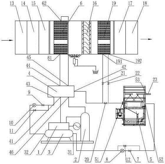
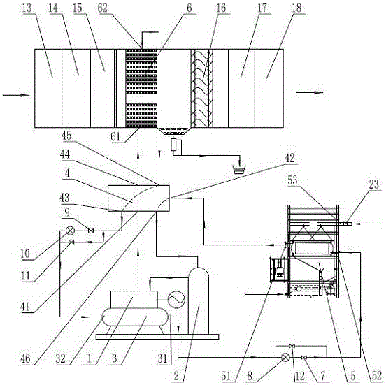
[0020] See figure 1 , the present invention includes a compressor 1, a separation tank 2 and a liquid storage tank 3, the output end of the compressor 1 is connected to the first port 41 of the first reversing valve 4, and the second port 42 of the first reversing valve 4 is connected to the dew point indirect The first port 51 of the evaporative cooling device 5, the second port 52 of the dew point indirect evaporative cooling device 5 communicates with the first port 31 of the liquid storage tank 3 through the first valve 7 and the first throttle valve 8, and the first port 31 of the liquid storage tank 3 The second port 32 communicates with the third port 43 of the first reversing valve 4 through the second valve 9 and the second throttle valve 10, and the fourth port 44 of the first reversing valve 4 is connected to the first plate-fin...


PUM


Abstract

A novel air conditioner dehumidification unit adopts the structure that a compressor, a separating tank and a liquid storage tank are respectively connected with three ports of a reversing valve, and the other three ports of the reversing valve are respectively connected with two ports of first plate fin type heat exchangers and one end of a dew point indirect evaporative cooling device; and the other end of the dew point indirect evaporative cooling device is communicated with the liquid storage tank; the separating tank is communicated with the compressor; the first plate fin type heat exchangers are arranged on the function sections of a combined type air-handling unit; a second throttle valve is arranged on a connecting pipeline of the liquid storage tank and the reversing valve; a first throttle valve is arranged on the connecting pipeline of the dew point indirect evaporative cooling device and the liquid storage tank; in a refrigeration working condition, the second throttle valve works, and in the heating working condition, the first throttle valve works; and in field where dehumidification is required, second plate fin type heat exchangers are additionally arranged on the function sections of the combined type air-handling unit. According to the unit provided by the invention, the cold / hot water circulating system is saved, three working conditions of refrigeration, heating and dehumidification are realized, the heat exchange efficiency is high, and the remarkable effects of energy conservation and emission reduction can be achieved.

Description

technical field [0001] The invention relates to the technical field of large-scale air-conditioning units, in particular to a high-efficiency and energy-saving air-conditioning dehumidification unit that adopts the combination of evaporative cooling and compression refrigeration, can realize three working conditions of refrigeration, heating and dehumidification. Background technique [0002] Large-scale air-conditioning units used in industrial or public buildings generally adopt the air-conditioning system of "refrigeration host + air-conditioning terminal", and because of its large cooling capacity, the refrigeration host generally uses water-cooled chillers, of which water-cooled screw chillers are used See more. Because the water-cooled chiller uses circulating cooling water to remove heat, it is necessary to set up a cooling water circulation system and a cooling tower. The cooling tower is used to cool down the cooling water of the chiller, and the cooling water pump ...

Claims


Application Information

Patent Timeline
Patent Type & Authority Patents(China)
IPC IPC(8): F24F5/00F24F13/30
Inventor 张宜万翟颖萍边晓伟陈立新漆林宝
Owner 无锡金龙石化冶金设备制造有限公司
Why Eureka
Try Eureka