Pipeline flowing stabilization control method

A stable control method and stable control technology, applied in the direction of liquid/fluid solid measurement, measuring devices, instruments, etc., can solve the problems of large space, long construction period, high cost, etc., and achieve simple control, low cost, and simple structural design Effect

Active Publication Date: 2013-09-18
NAT UNIV OF DEFENSE TECH
View PDF5 Cites 10 Cited by
  • Summary
  • Abstract
  • Description
  • Claims
  • Application Information

AI Technical Summary

Problems solved by technology

[0005] The purpose of the present invention is to provide a pipeline flow stability control method to solve technical problems such as large space required for building water towers, high cost, and long construction period.

Method used


Image

  • Pipeline flowing stabilization control method
  • Pipeline flowing stabilization control method
  • Pipeline flowing stabilization control method

Examples


Embodiment Construction

[0028] The embodiments of the present invention will be described in detail below with reference to the accompanying drawings, but the present invention can be implemented in many different ways defined and covered by the claims.

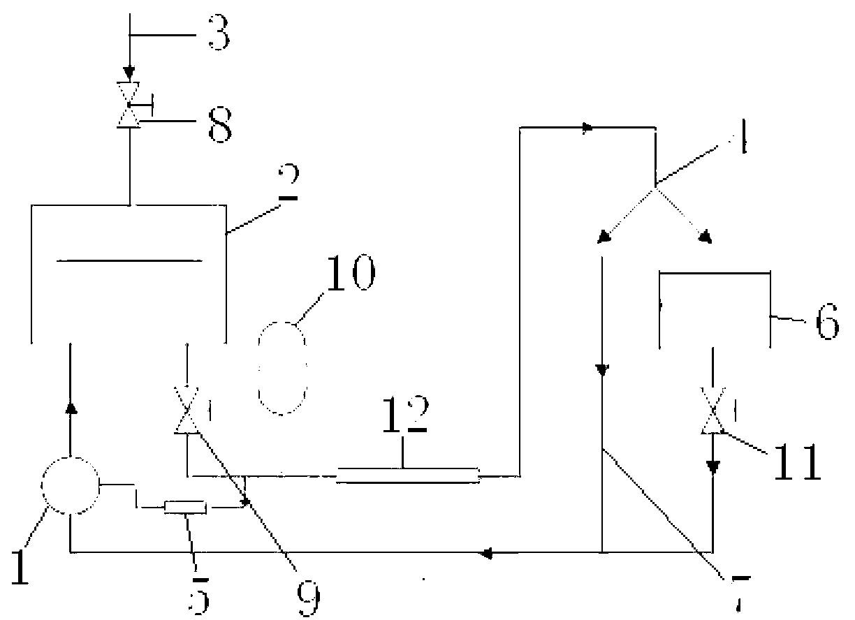
[0029] figure 1 It is a schematic diagram of pipeline flow stability control in the flow calibration water conservancy system of the preferred embodiment of the present invention, such as figure 1 The shown water conservancy system includes a water pump 1, the water pump 1 is connected to a surge tank 2, an air inlet 3 is arranged on the surge tank 2, the surge tank 2 is connected to a commutator 4, and there is a gap between the surge tank 2 and the commutator 4. A pressure tester 5 is provided, and the pressure tester 5 is connected to and controls the water pump 1 , and the commutator 4 is connected to the water pump 1 through a calibration system 6 and a bypass pipeline 7 respectively. The air inlet 3 is provided with an air inlet valve 8 . A ...


PUM


Abstract

The invention discloses a pipeline flowing stabilization control method which comprises the following steps: establishing a hydraulic system; setting a water pump and a pressure stabilizing tank in the hydraulic system; starting the water pump, and feeding water into the pressure stabilizing tank; charging a certain amount of gas into the pressure stabilizing tank, at this moment the pressure stabilizing tank is filled with a certain amount of gas and water; releasing a water control valve, feeding the water into a flowing stabilization control section from the pressure stabilizing tank, monitoring the water pressure through a pressure tester in real time, wherein the pressure tester is connected with a control unit so as to control the water pump, and the pressure tester is automatically started or is used for adjusting or stopping the water pump; performing compensating by the water pressure fluctuation through an energy accumulator to a certain extent; feeding the water flow in the pipeline into a commutator through the flowing stabilization control section and into a calibration system through the commutator so as to reach a calibrated acquisition quantity, and turning the commutator to a bypass so as to feed the water back to the water pump; and feeding the water back to the water pump after the calibration system accomplishes the test. According to the method, stable flowing is obtained by employing a combined mode of an electronic control method and an energy accumulator, the structural design and the control are simple, the occupied space is small, and the mounting and the debugging are convenient.

Description

technical field [0001] The invention relates to the technical field of hydraulic control, in particular to a method for controlling the stability of pipeline flow in a water conservancy system. Background technique [0002] The hydraulic test system is a comprehensive platform for the study of fluid flow and related applications. The calibration and verification of flow measurement devices is an important application field of hydraulic systems. Since the flow measurement is greatly affected by the external environment, including: temperature, viscosity, and flow field distribution in the flow measurement pipeline, the flow measurement device needs to pass the actual flow calibration of the hydraulic calibration system. During the calibration process, a stable pipeline flow is a prerequisite for the calibration of flow measurement devices. [0003] Currently, the steady pipeline flow is mainly provided by the water tower, and the water is pumped from the storage tank to the...

Claims


Application Information

Patent Timeline
Patent Type & Authority Applications(China)
IPC IPC(8): G01F25/00
Inventor 赵勇陈勇陈小前黄奕勇韩伟张翔姚雯
Owner NAT UNIV OF DEFENSE TECH
Why Eureka
Try Eureka