Partial discharge electro-acoustic signals synchronous monitoring device for CPLD (complex programmable logic device)-based transformer
A partial discharge and monitoring device technology, which is applied in the direction of measuring devices, instruments, and testing dielectric strength, etc., can solve problems such as low accuracy and low reliability, achieve high working stability, improve accuracy and real-time performance , Improve the effect of reliability and flexibility
- Summary
- Abstract
- Description
- Claims
- Application Information
AI Technical Summary
Problems solved by technology
Method used
Image
Examples
Embodiment 1
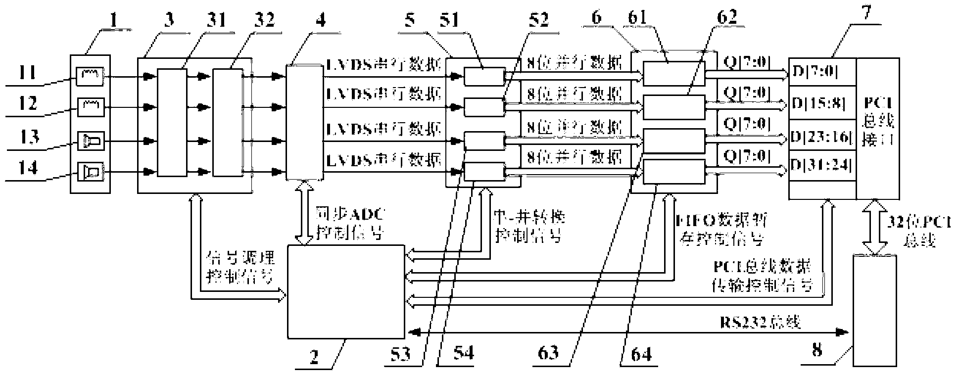
[0030] A CPLD-based transformer partial discharge electric-acoustic signal synchronous monitoring device, comprising a sensor module 1, a signal conditioning module 3, a four-channel synchronous sampling ADC 4 and a host computer 8; it is characterized in that: the device also includes a CPLD control module 2, Deserializer module 5, FIFO memory 6 and PCI bus interface circuit 7; According to the transmission flow direction of signal, described sensor module 1, signal conditioning module 3, four-channel synchronous sampling ADC 4, deserializer module 5, FIFO memory 6 , PCI bus interface circuit 7 and host computer 8 are connected successively, specifically:
[0031] The sensor module 1 is provided with four sensors, which are Rogowski coil sensor A 11, Rogowski coil sensor B 12, ultrasonic sensor A 13 and ultrasonic sensor B 14, wherein Rogowski Coil sensor A 11 and Rogowski coil sensor B 12 are respectively installed at the neutral point of the high and low voltage sides of th...
Embodiment 2
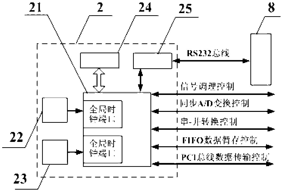
[0036] The difference between this embodiment and embodiment 1 is: described CPLD control module 2 is connected with CPLD chip 21 and high-frequency active crystal oscillator 22, low-frequency active crystal oscillator 23, man-machine interface 24, RS232 respectively connected with CPLD chip 21. Interface circuit 25 forms; The I / O port of described CPLD chip 21 is respectively connected with the control terminal and RS232 interface of signal conditioning module 3, four-channel synchronous sampling ADC 4, deserializer module 5, FIFO memory 6, PCI bus interface circuit 7 The data end of circuit 25 is bidirectionally connected, and described RS232 interface circuit 25 is bidirectionally connected with host computer 8 by RS232 bus, and described high-frequency active crystal oscillator 22, low-frequency active crystal oscillator 23 are connected with the global clock port of CPLD chip 21 respectively.
Embodiment 3
[0038] as attached figure 1 As shown, a CPLD-based transformer partial discharge electric-acoustic signal synchronous monitoring device includes a sensor module 1, a CPLD control module 2, a signal conditioning module 3, a four-channel synchronous sampling ADC 4, a deserializer module 5, and a FIFO memory 6 , PCI bus interface circuit 7 and host computer 8; Described sensor module 1 is provided with four sensors, is respectively Rogowski coil sensor A 11, Rogowski coil sensor B 12, ultrasonic sensor A 13 and ultrasonic sensor Sensor B 14, among them, Rogowski coil sensor A 11 and Rogowski coil sensor B 12 are respectively installed at the neutral point of the high and low voltage side of the transformer, and the frequency bandwidth is set to 10kHz ~ 10MHz, respectively It is used to transform the pulse current at the grounding point of the high and low voltage side of the transformer into a voltage signal for A / D conversion; the ultrasonic sensor A 13 and the ultrasonic sensor...
PUM
| Property | Measurement | Unit |
|---|---|---|
| Bandwidth | aaaaa | aaaaa |
| Bandwidth | aaaaa | aaaaa |
Abstract
Description
Claims
Application Information
 - R&D
- Intellectual Property
- Life Sciences
- Materials
- Tech Scout
- Unparalleled Data Quality
- Higher Quality Content
- 60% Fewer Hallucinations
Browse by: Latest US Patents, China's latest patents, Technical Efficacy Thesaurus, Application Domain, Technology Topic, Popular Technical Reports.
© 2025 PatSnap. All rights reserved.Legal|Privacy policy|Modern Slavery Act Transparency Statement|Sitemap|About US| Contact US: help@patsnap.com


