Ultraviolet image fault positioning and processing system and ultraviolet image fault positioning and processing method both used for corona detection

An ultraviolet image and fault location technology, applied in the field of ultraviolet spectrum detection, can solve the problems of large noise, system imaging quality impact, poor imaging quality, etc., and achieve the effect of suppressing thermal noise

Active Publication Date: 2013-09-18
NANJING SHUNTAI TECH
View PDF9 Cites 25 Cited by
  • Summary
  • Abstract
  • Description
  • Claims
  • Application Information

AI Technical Summary

Problems solved by technology

The low-end UV image intensifier has a lot of noise and the image quality is poor; in addition, the performance index of the UV filter cannot reach the high-end advanced level.
Therefore, under the existing condition

Method used


Image

  • Ultraviolet image fault positioning and processing system and ultraviolet image fault positioning and processing method both used for corona detection
  • Ultraviolet image fault positioning and processing system and ultraviolet image fault positioning and processing method both used for corona detection
  • Ultraviolet image fault positioning and processing system and ultraviolet image fault positioning and processing method both used for corona detection

Examples


Embodiment Construction

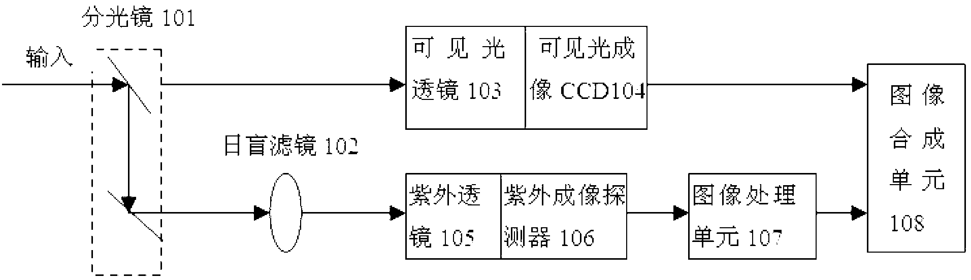
[0026] figure 1 It is a schematic structural diagram of an ultraviolet image fault location system according to an embodiment of the present invention. Such as figure 1 As shown, the ultraviolet imaging system includes a spectroscope 101, a solar blind filter 102, a visible light lens 103, a visible light imaging CCD 104, an ultraviolet lens 105, an ultraviolet imaging detector 106, an image processing unit 107, and an image synthesis unit 108.

[0027] Such as figure 1 As shown, the target light radiation signal is divided into two paths of transmitted light and reflected light after being split by the spectroscope 101, and the transmitted light passes through the visible light lens 103 and enters the visible light imaging CCD 104. The reflected light first passes through the solar-blind filter 102, and then passes through the ultraviolet lens 105 to enter the ultraviolet imaging detector 106. According to an embodiment of the present invention, the field of view range of the ul...


PUM


Abstract

The invention provides a ultraviolet image fault positioning system which comprises a light splitter, a solar blind filter, a visible lens, a visible imaging CCD (charge coupled device), an ultraviolet lens, a ultraviolet image detector, a image processing unit and an image synthesis unit. The light splitter splits target light radiation signals into two branches of light including transmission light and reflection light, the transmission light penetrates the visible lens to enter the visible imaging CCD, the reflection light passes the solar blind filter and then penetrates the ultraviolet lens to enter, and ultraviolet images of the ultraviolet image detector after being performed image processing by the image processing unit together with ordinary images formed by the visible imaging CCD are output to the image synthesis unit to be processed to acquire synthesized output images. Ultraviolet dynamic images are analyzed and processed, so that background noise and thermal noise of the ultraviolet image detector are effectively inhibited; after the images are processed, corona discharging image signals of high-voltage equipment can be clearly observed, so that accuracy in positioning of high-voltage discharging fault points is effectively improved.

Description

Technical field [0001] The present invention relates to corona detection technology, in particular to an ultraviolet spectrum detection technology for corona detection. Background technique [0002] When the electric field strength on the surface of the overhead transmission line exceeds the free strength of the air molecules, the air molecules will be ionized. At this time, you can hear the "stab" discharge sound, smell the odor of ozone, and you can see the emission around the wire at night. Blue-violet fluorescence, this phenomenon is called "corona discharge" or "corona" for short. Corona consumes electric energy, and the pulsed electromagnetic waves generated during corona discharge will interfere with radio and high-frequency communications. In addition, corona will corrode the surface of the wire, thereby reducing the service life of the wire. [0003] At present, line inspections of overhead transmission lines mainly adopt far-infrared telescopes, ultrasonic corona detect...

Claims


Application Information

Patent Timeline
IPC IPC(8): G01R31/12
Inventor 张立强张玉钧蔡毅敏李宏斌
Owner NANJING SHUNTAI TECH
Why Eureka
Try Eureka