Ultra wideband multi-band dual-polarized antenna

A dual-polarized antenna and ultra-wideband technology, which is applied to antenna unit combinations, antennas, and antenna couplings with different polarization directions, can solve the problems of poor isolation between high-frequency dipole ports and low-frequency dipole ports, antenna frontal area, volume and The problems of increased quality and narrow bandwidth of the microstrip antenna frequency band achieve the effects of compact structure, increased dipole arm length, and bandwidth expansion

Active Publication Date: 2013-09-18
TONGYU COMM INC
View PDF5 Cites 37 Cited by
  • Summary
  • Abstract
  • Description
  • Claims
  • Application Information

AI Technical Summary

Problems solved by technology

[0004] Although the above three structures can broaden the frequency bandwidth of the antenna, they all have their limitations, specifically: the frequency bandwidth of the microstrip antenna in the first structure is relatively narrow, and the isolation between the high-frequency oscillator port and the low-frequency oscillator port is also poor.
Although the second structure can well make up for the deficiency of the microstrip antenna, in order to ensure the electrical performance indicators of each frequency band and reduce the mutual influence between the oscillators of different frequency bands, the width of the antenna must be increased, so the windward area and volume of the antenna and quality increased accordingly
The distance between the high-frequency and low-frequency oscillators in the coaxial ultra-broadband multi-frequency dual-polarized antenna of the third structure should not be too small, otherwise there will be strong electromagnetic coupling between the low-frequency oscillator and the high-frequency oscillator, which will seriously interfere with electromagnetic waves. radiation, so its windward area is still large

Method used


Image

  • Ultra wideband multi-band dual-polarized antenna
  • Ultra wideband multi-band dual-polarized antenna
  • Ultra wideband multi-band dual-polarized antenna

Examples


Embodiment Construction

[0066] In order to make the object, technical solution and advantages of the present invention clearer, the present invention will be described in further detail below with reference to the accompanying drawings and preferred embodiments. However, it should be noted that many of the details listed in the specification are only for readers to have a thorough understanding of one or more aspects of the present invention, and these aspects of the present invention can be implemented even without these specific details.

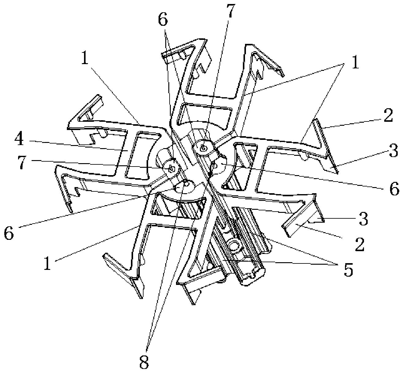
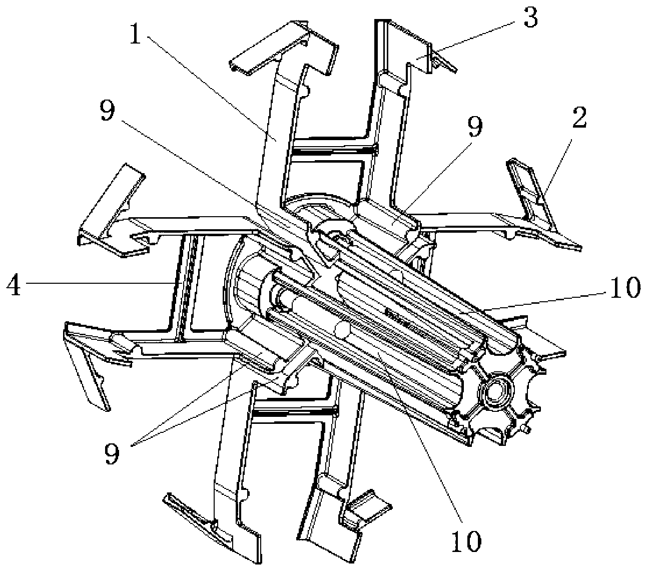
[0067] In the embodiment of the present invention, it is considered to set a bowl-shaped radiator on the periphery of the high-frequency radiation unit to focus the energy of the radiation field, thereby expanding the high-frequency bandwidth of the high-frequency radiation unit; The unit is insulated from the reflector, so that the high-frequency radiation unit and the low-frequency radiation unit can avoid secondary radiation from the high-frequency electromagne...


PUM


Abstract

The invention discloses an ultra wideband multi-band dual-polarized antenna, which comprises a reflection board, at least one low-frequency radiation unit and at least one high-frequency radiation unit, wherein the low-frequency radiation units and the high-frequency radiation units are arranged on the reflection board; the high-frequency radiation units are adjacent to the low-frequency radiation units; and each high-frequency radiation unit comprises a high-frequency vibrator insulated from the top surface of the reflection board and a bowl-shaped radiator arranged on the periphery of the high-frequency vibrator. According to the ultra wideband multi-band dual-polarized antenna, by the high-frequency radiation units, an operating frequency range is widened, and meanwhile, coupling with the low-frequency radiation units can be effectively reduced; and by the low-frequency radiation units, an operating frequency range is widened, and meanwhile, the radiation efficiency can be effectively improved. Therefore, the bandwidths of the low-frequency operating frequency range and the high-frequency operating frequency range can be greatly increased, and the ultra wideband multi-band dual-polarized antenna has the advantages of small frontal area and compact structure.

Description

technical field [0001] The invention relates to the field of mobile communication base station antennas, in particular to an ultra-wideband multi-frequency dual-polarization antenna. Background technique [0002] With the continuous development of mobile communication technology, the communication base station has put forward higher and higher requirements for the index requirements of the base station antenna, especially the gain, bandwidth characteristics, half-power angle fluctuation characteristics with frequency, and cross-polarization characteristics. [0003] Most existing base station antennas use dual-frequency ultra-wideband multi-frequency dual-polarized antennas to widen their frequency bandwidth. The high and low-frequency oscillators of existing dual-frequency ultra-wideband multi-frequency dual-polarized antennas mainly adopt the following structural forms: The microstrip radiating unit is used as a low-frequency radiating unit. The high-frequency vibrator is ...

Claims


Application Information

Patent Timeline
Patent Type & Authority Applications(China)
IPC IPC(8): H01Q1/36H01Q1/52H01Q19/10H01Q21/30H01Q21/24
Inventor 岳彩龙张毅万乐乐韩波李山山孔庆泉刘木林吴中林
Owner TONGYU COMM INC
Why Eureka
Try Eureka