Laser diode array and laser diode unit

A technology of laser diodes and arrays, used in lasers, laser devices, laser parts, etc., can solve problems such as glare characteristics and deterioration of screens, and achieve the effects of improving heat dissipation efficiency, reducing coherence, and suppressing characteristic deterioration.

Inactive Publication Date: 2013-09-18
SONY CORP
View PDF1 Cites 8 Cited by
  • Summary
  • Abstract
  • Description
  • Claims
  • Application Information

AI Technical Summary

Problems solved by technology

[0003] However, when a laser diode is used as a light source, there are two problems, namely, screen glare (speckle noise) and deterioration of characteristics due to heat generation

Method used


Image

  • Laser diode array and laser diode unit
  • Laser diode array and laser diode unit
  • Laser diode array and laser diode unit

Examples


Embodiment approach

[0026] 1-1. Configuration of Laser Diode Array

[0027] 1-2. Manufacturing method

[0028] 2. Modification example

Embodiment approach )

[0031] (1-1. Arrangement of Laser Diode Array)

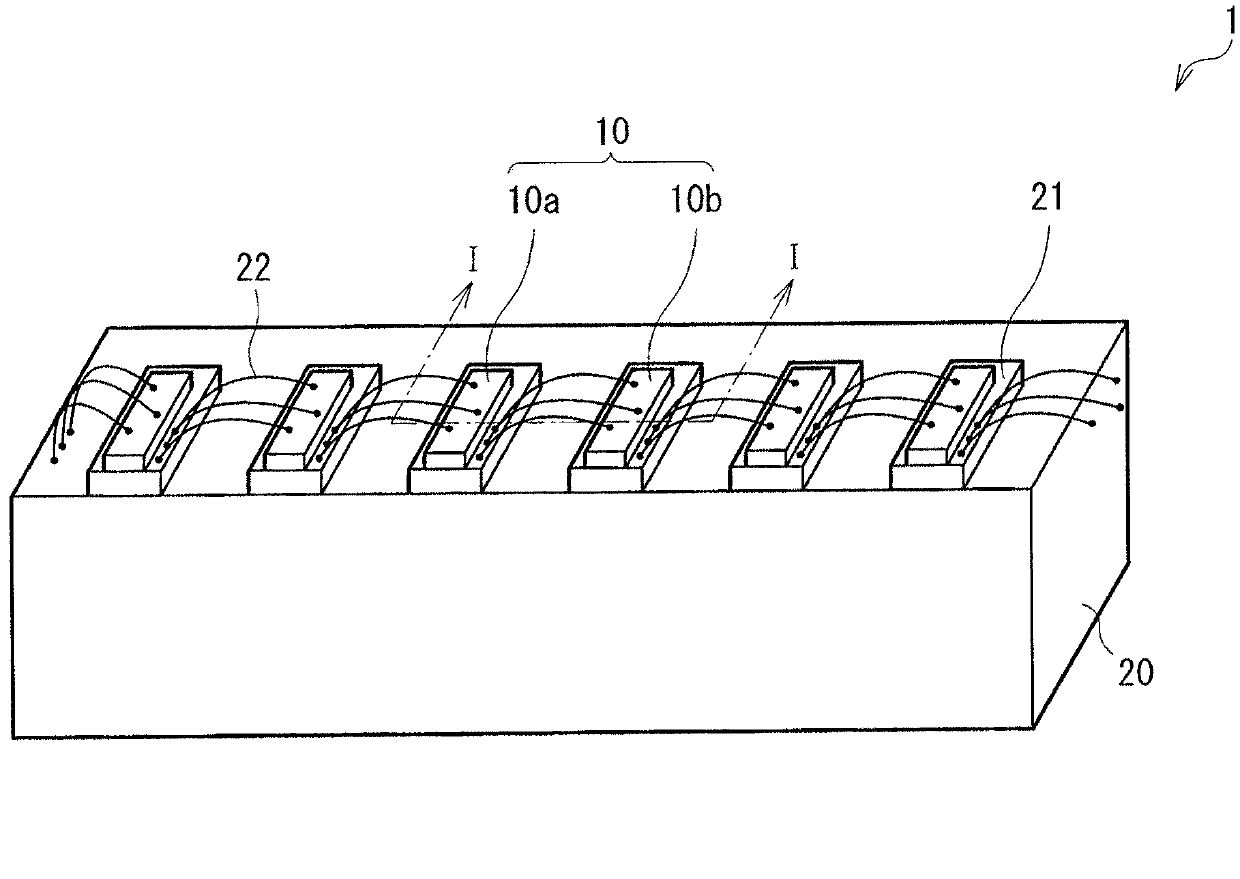
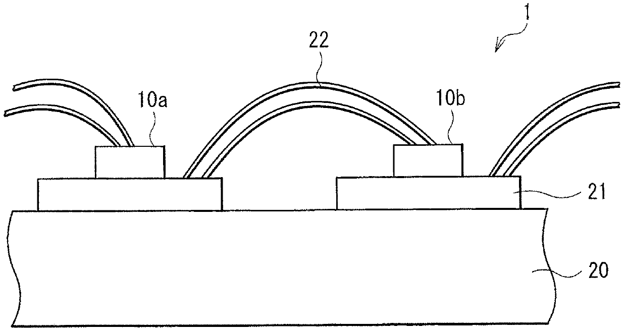
[0032] figure 1 The overall structure of a laser diode array (laser diode array 1 ) according to an embodiment of the present disclosure is shown. figure 2 is along figure 1 The cross-sectional structure taken along the line I-I. In the laser diode array 1 , a plurality of laser diode devices (devices 10 ) are mounted on a heat dissipator (heat sink 20 ) in one direction with bases 21 in between. The bases 21 are provided independently of each other, and in this case, one device 10 is provided on one base 21 . The devices 10 are connected in series with each other. More specifically, as will be described in detail later, for example, a first electrode of a pair of electrodes of the device 10a (for example, the p-side electrode 13) and a second electrode of a pair of electrodes of the device 10b (for example, the n-side electrode 14 ) are electrically connected to each other by wiring 22 (refer to figure 2 ).

[0033] ...


PUM


Abstract

A laser diode array includes: a heat dissipator; a plurality of submounts disposed independently of one another on the heat dissipator; and a plurality of laser diode devices including two or more kinds of laser diode devices with different oscillation wavelengths, the laser diode devices being disposed on the respective submounts, and being electrically connected to one another.

Description

technical field [0001] The present disclosure relates to a laser diode array comprising a plurality of laser diode devices on a heat sink, and to a laser diode unit comprising the laser diode array. Background technique [0002] Laser diodes are used as light sources for displays and the like because of their small light-emitting points and sharp spectra (its high color rendering). For example, in Japanese Unexamined Patent Application Publication No. 2006-32406, a laser array including a plurality of laser diode devices arranged one-dimensionally is used as a high-power laser. [0003] However, when a laser diode is used as a light source, there are two problems, namely, screen glare (speckle noise) and deterioration of characteristics due to heat generation. [0004] A typical laser diode has a characteristic that its oscillation wavelength shifts to a longer wavelength as the internal temperature of the active layer increases. For example, in Japanese Unexamined Patent ...

Claims


Application Information

Patent Timeline
Patent Type & Authority Applications(China)
IPC IPC(8): H01S5/40H01S5/022
CPCH01S5/02469H01S5/02476H01S5/2231H01S5/4018H01S5/4031H01S5/405H01S5/4087H01L2224/48091H01S5/0237H01L2924/00014H01S5/024
Inventor 若林和弥大野智辉
Owner SONY CORP
Why Eureka
Try Eureka