

Unified power flow controller adopting modular structure and starting method for unified power flow controller
A power flow controller and modular technology, applied in the direction of power transmission AC network, etc., can solve the problems of limited controllable range, charging of series converters, etc., and achieve the effect of improving device reliability, high reliability, and simple control method
- Summary
- Abstract
- Description
- Claims
- Application Information
AI Technical Summary
Problems solved by technology
Method used
Image

Examples
Embodiment 1
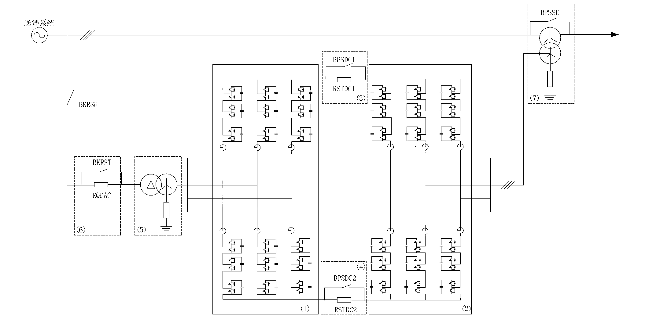
[0070] Put in the DC current limiting resistor current limiting start to limit the current after the converter is unlocked when the sub-module is low voltage; the circuit structure is as follows figure 1 shown;
[0071] When the parallel converter makes the sub-module capacitor voltage reach the rated value through controllable rectification, the capacitor voltage of the MMC module on the series side reaches half of the rated value. At this time, the series-side MMC pulse is unlocked, and the sub-modules are divided into two groups for input. At the same time, a current-limiting resistor is put into the DC side to limit the inrush current. The series-side MMC can absorb electric energy through the DC side to charge the module capacitor. When the number of modules put into each group of each phase of the MMC on the series side is N, the capacitors of the N modules can be charged to the rated voltage. Through the two-stage switching and alternate charging methods, the capacitor...
Embodiment 2
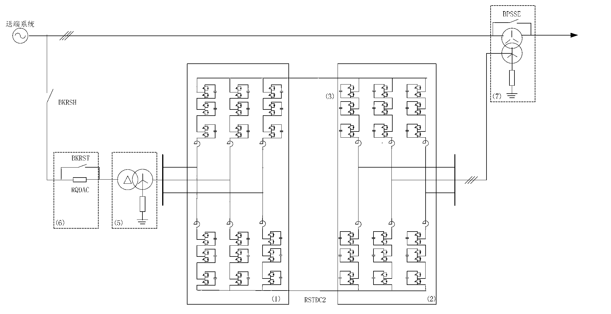
[0077] Putting in the AC current limiting resistor to start the current limit, the circuit structure is as follows figure 2 shown. This scheme omits the DC current limiting resistor and its bypass switch, but it will increase the valve's requirements for voltage and current tolerance. In the uncontrolled rectification stage, a current-limiting resistor is required on the AC side, and the resistor is bypassed after the uncontrolled rectification ends. This resistor can be switched back on to limit inrush current when controlled rectification begins.
[0078] The full charging procedure is as follows:
[0079] The parallel converter triggers pulse unlocking, and uses constant DC voltage control until the AC side charges the capacitor voltage of the parallel converter sub-module to the rated value. At this time, the capacitor voltage of the series converter sub-module is charged to half of the rated value.
[0080] Disconnect the soft start resistor bypass switch BKRST;
[0...
PUM
 Abstract
Description
Claims
Application Information