Drilling tool for processing annular groove

An annular groove and drill technology, which is used in metal processing equipment, drill repairs, drilling tool accessories, etc., can solve the problems of difficulty in mass production, long cost of laser grooving, and difficulty in mass production, so as to reduce material costs. , The effect of stable processing and high processing accuracy

Active Publication Date: 2013-09-25
SHANGHAI FAST PCB CIRCUIT TECH CORP LTD
View PDF7 Cites 1 Cited by
  • Summary
  • Abstract
  • Description
  • Claims
  • Application Information

AI Technical Summary

Problems solved by technology

[0002] At present, most microwave PCB boards with circular steps adopt laser slotting or milling machine front and back milling. Laser slotting takes a long time and costs a lot, and mass production is difficult to achieve.
The forward and reverse milling of the milling machine takes a long time, and is affected by the flatness of the milling machine and the rotation accuracy of the spindle, it is also difficult to achieve mass production, and the quality will also be affected

Method used


Image

  • Drilling tool for processing annular groove
  • Drilling tool for processing annular groove

Examples


Embodiment

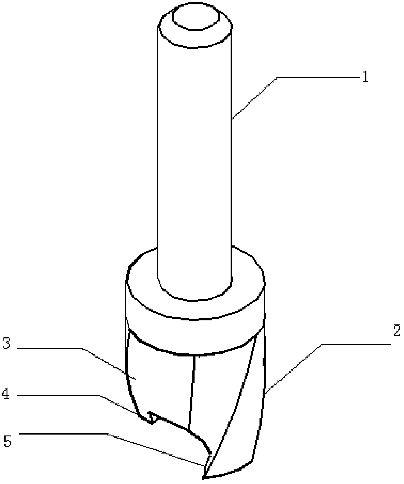
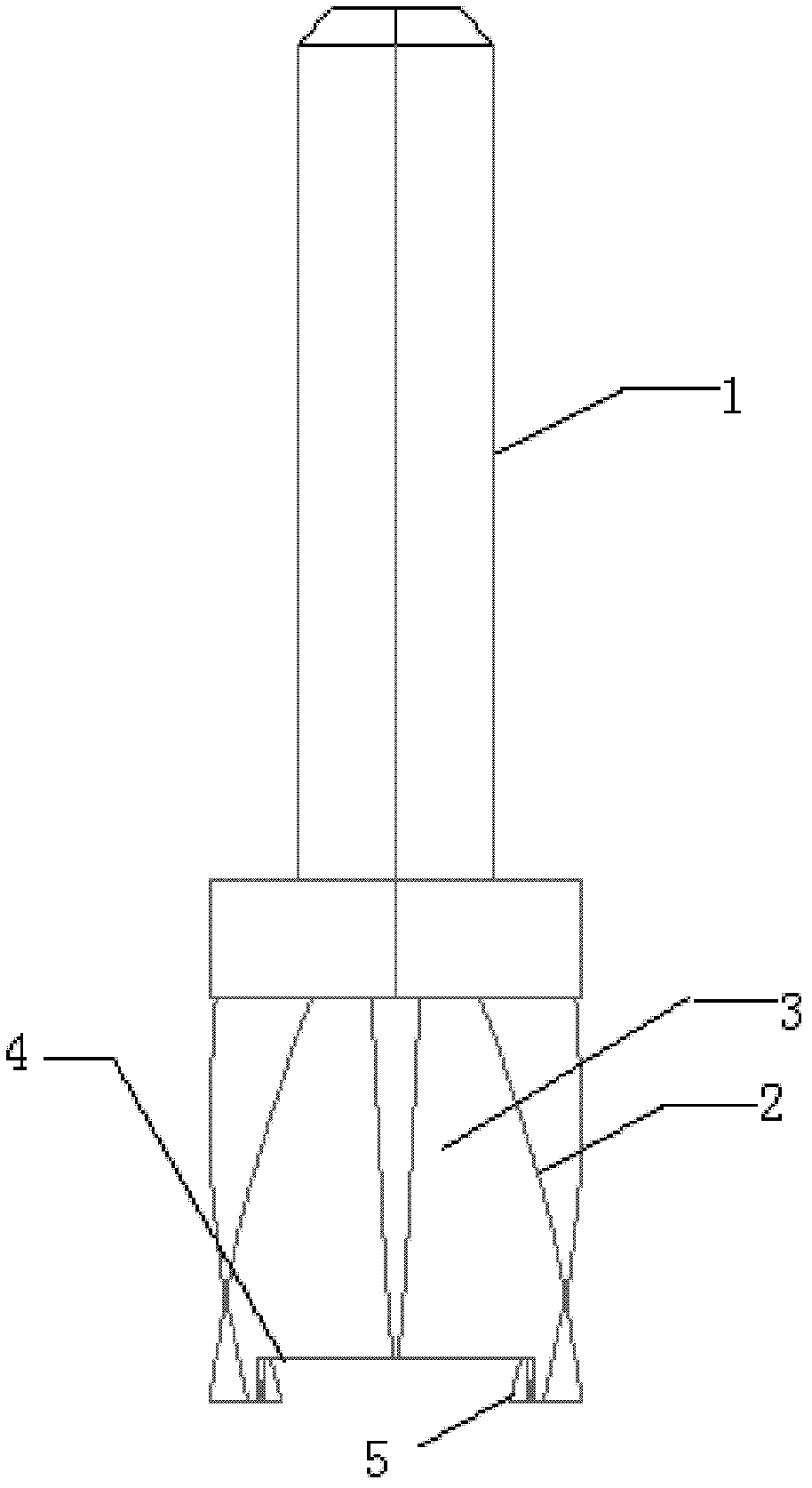
[0020] Such as figure 1 As shown, a drill bit for machining annular grooves includes a tool handle 1 and a cutter head with a rotation angle of 65°. 3. The flute 3 is U-shaped, with an outer blade 2 on its edge, and a cutting groove 4 at the lower end of the cutter head. The cutting groove 4 is arc-shaped, and its side wall is provided with an inner blade 5 and an outer blade 2 It is used to process the outer wall of the annular groove, and the inner blade 5 is used to process the inner wall of the annular groove. The outer blade 2 and the inner blade 5 cut the workpiece along the rotation direction of the drill, and drill annular grooves of different depths according to the thickness of the workpiece. , and the chips generated by cutting are discharged from the chip flute 3.

[0021] The cutter head is made of hard alloy processed into particles, which has high hardness and precision. It can process PCB boards of different materials. It can be processed continuously for more...


PUM

PropertyMeasurementUnit
Lengthaaaaaaaaaa
Lengthaaaaaaaaaa

Abstract

The invention relates to a drilling tool for the processing of an annular groove, which comprises a tool handle and a tool bit, wherein the tool bit is arranged at the lower end of the tool handle, a chip discharging groove is formed in the side wall of the tool bit, an outer tool blade is arranged on the edge of the chip discharging groove, a cutting groove is formed in the end part of the tool bit, an inner tool blade is arranged on the side wall of the cutting groove, the outer tool blade is used for processing the outer sidewall of the annular groove, the inner tool blade is used for processing the inner sidewall of the annular groove, the outer tool blade and the inner tool blade cut a workpiece in the rotation direction of the drilling tool, and chips generated in cutting is discharged through the chip discharging groove. Compared with the prior art, the drilling tool has the advantages of high processing precision, stable processing, low cost and the like.

Description

technical field [0001] The invention relates to a drill, in particular to a drill used for machining annular grooves. Background technique [0002] At present, most microwave PCB boards with circular steps adopt laser slotting or milling machine front and back milling. Laser slotting takes a long time and costs a lot, and mass production is difficult to achieve. The front and back milling of the milling machine takes a long time, and is affected by the flatness of the milling machine and the rotation accuracy of the spindle, it is also difficult to achieve mass production, and the quality will also be affected. Contents of the invention [0003] The object of the present invention is to provide a drill for machining annular grooves in order to overcome the above-mentioned defects in the prior art. [0004] The purpose of the present invention can be achieved through the following technical solutions: [0005] A drill bit for processing annular grooves, comprising a handl...

Claims


Application Information

Patent Timeline
IPC IPC(8): B23B51/00
Inventor 唐永成
Owner SHANGHAI FAST PCB CIRCUIT TECH CORP LTD
Why Eureka
Try Eureka