Supercharge Your Innovation With Domain-Expert AI Agents!

Wind driven generator wind wheel provided with straight panel wind wheel blades

A technology of wind turbines and wind rotor blades, applied in the field of wind rotors, can solve the problems of narrow effective use range of wind speed, low efficiency of wind energy absorption, waste of wind energy resources, etc., achieve reduced centrifugal force, enhanced ability to absorb strong wind resources, and reduce sharp effect

Active Publication Date: 2013-09-25
解宏
View PDF5 Cites 0 Cited by
  • Summary
  • Abstract
  • Description
  • Claims
  • Application Information

AI Technical Summary

Problems solved by technology

[0004] The purpose of the present invention is to solve the problems of low wind energy absorption efficiency, easy fatigue, narrow effective utilization range of wind speed and high cost of the existing propeller-type wind rotor blades, which cause waste of wind energy resources, and further provide a wind turbine with a straight blade. wind turbine blade wind turbine

Method used


Image

  • Wind driven generator wind wheel provided with straight panel wind wheel blades
  • Wind driven generator wind wheel provided with straight panel wind wheel blades
  • Wind driven generator wind wheel provided with straight panel wind wheel blades

Examples


specific Embodiment approach 1

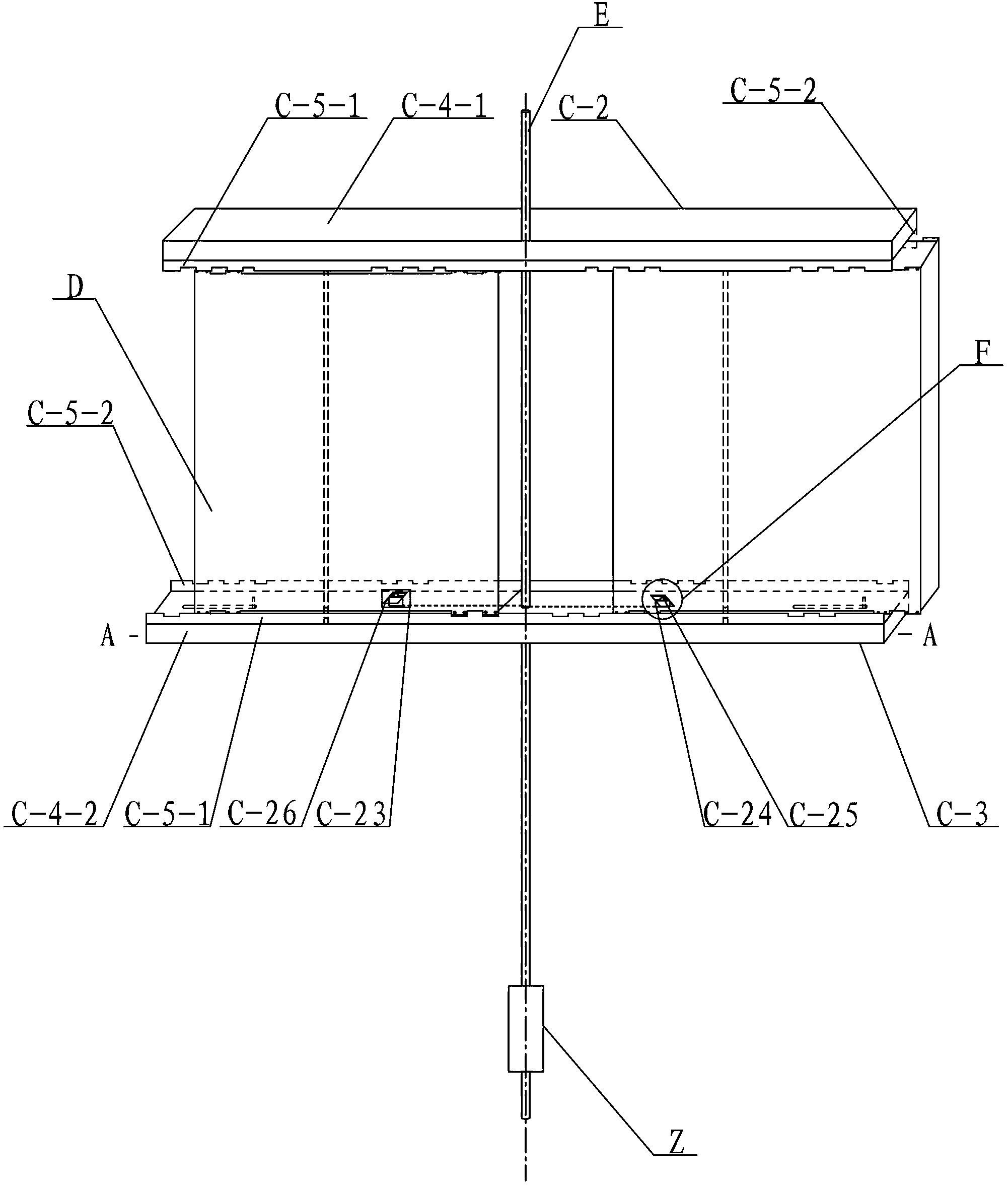
[0018] Specific implementation mode one: combine Figure 1-Figure 7 Describe this embodiment, this embodiment includes a tower body, a main shaft E and a plurality of straight wind rotor blades D, the main shaft E is vertically arranged, the tower body includes multiple sets of towers C, and one end of the multiple sets of towers C is fixed to the main shaft On E, the other ends of multiple sets of towers C are distributed horizontally and radially at equal angles relative to the main axis E, and each set of towers C is equipped with a straight wind rotor blade D,

[0019] Each group of towers C includes an upper tower C-2 and a lower tower C-3, and the upper tower C-2 and the lower tower C-3 are arranged relatively parallel up and down,

[0020] The upper tower C-2 includes a steel plate C-4-1, a first side plate C-5-1 and a second side plate C-5-2, and the first side plate C-5-1 and the second side plate C-5-2 is arranged on both sides of the steel plate C-4-1 in the length...

specific Embodiment approach 2

[0025] Specific implementation mode two: combination image 3 and Figure 4 This embodiment will be described. The transmission device in this embodiment includes a first wind rotor blade shaft C-6, a second wind rotor blade shaft C-7, a first pin shaft C-8, a second pin shaft C-9, and a first sprocket C-10 , Second sprocket C-11, third sprocket C-12, fourth sprocket C-13, bracket C-14, first gear C-15, second gear C-16, third gear C-17 , the fourth gear C-18, the first chain C-19, the second chain C-20 and the third chain C-21,

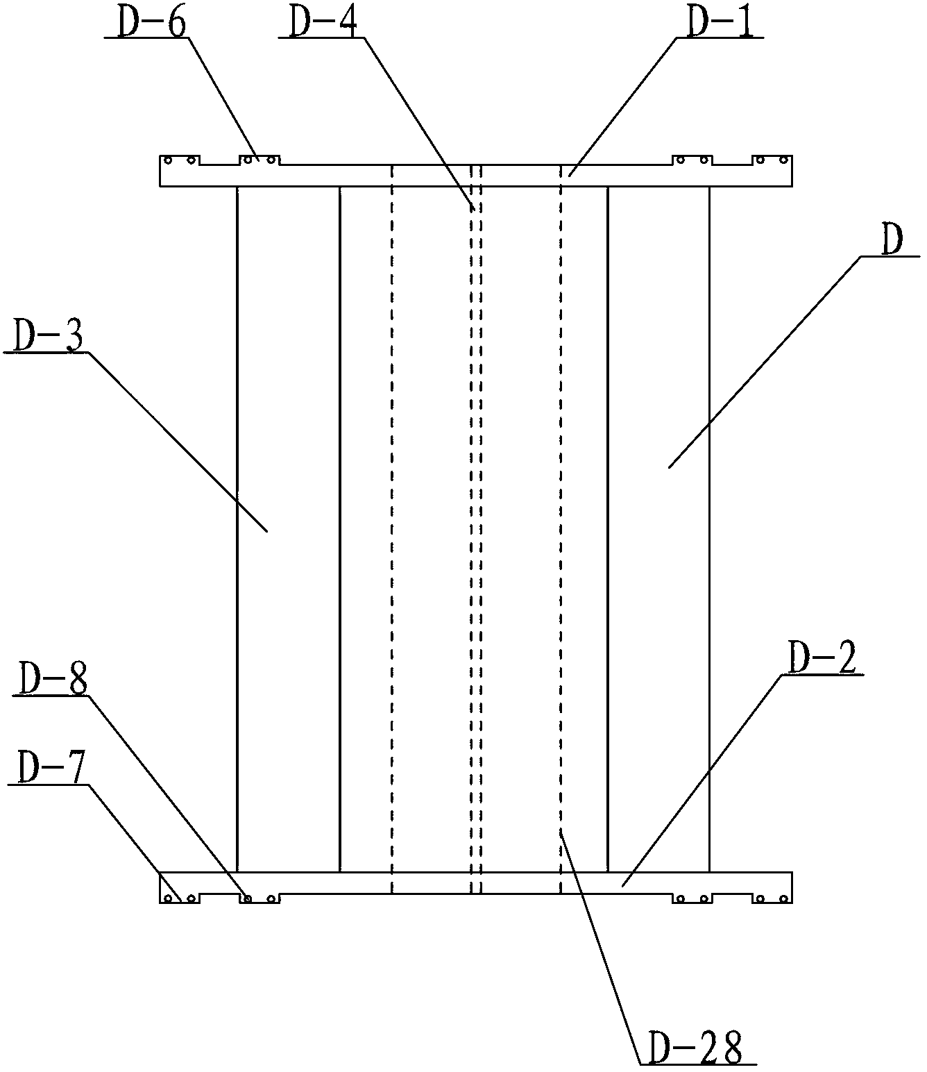
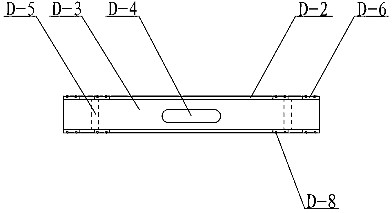
[0026] The first wind rotor blade axis C-6 and the second wind rotor blade axis C-7 are centered on the main axis E, and are vertically symmetrical and rotatable to pass through the steel plate C-4-1, the main block D-28 and the shell C -4-2, and the first wind rotor blade shaft C-6 or the second wind rotor blade shaft C-7 is fixedly connected with the main block D-28 in the double-sided retractable block D-3, the main block The sheet D-28 forms ...

specific Embodiment approach 3

[0029] Specific implementation mode three: combination image 3 and Figure 4 To illustrate this embodiment, the tower C of this embodiment also includes a limiting device, and the limiting device includes two limiting cards C-23. In the center, a limit card slot C-26 is symmetrically provided, and the middle part of the bracket C-14 is horizontally rotatably arranged on the main shaft E in the two opposite housings C-4-2, and the two sides of the bracket C-14 A limit card C-23 is respectively fixed on the upper end surface of each, and the limit card C-23 is movably arranged in the limit card slot C-26. In this way, under the drive of the straight wind rotor blade D, the separation or meshing of the first gear C-15 and the third gear C-17, and the second gear C-16 and the fourth gear C-18 are realized through the limit device . When a straight wind rotor blade D is at an angle of 0 degrees, the second limit card C-25 in the limit device is pressed by the straight wind roto...


PUM


Abstract

The invention relates to a wind wheel of a wind driven generator, in particular to a wind driven generator wind wheel provided with straight panel wind wheel blades. The wind driven generator wind wheel aims at solving the problems that an existing propeller type wind wheel blade is low in wind energy absorbing efficiency, fatigable, narrow in the effective utilization range of wind speed and high in manufacturing cost, and wind energy resources are wasted. The wind driven generator wind wheel comprises a tower body, a main shaft (E) and the straight panel wind wheel blades (D), wherein the main shaft (E) is vertically arranged, the tower body comprises a plurality of sets of tower frames (C), one ends of the sets of tower frames (C) are fixed on the main shaft (E), the other ends of the sets of tower frames (C) are distributed in an equiangular horizontal radiating mode relative to the main shaft (E), and each set of tower frame (C) is provided with one straight panel wind wheel blade (D). The blade point speed and the centrifugal force of the wind driven generator wind wheel in the rotating process are both lowered, so that the capacity of absorbing strong wind resources by the wind driven generator wind wheel is greatly enhanced. By means of the telescopic motion of telescopic stopping slices at the two sides, the length of the wind wheel blades is adjusted, and absorption and utilization of gentle wind resources are improved. The wind driven generator wind wheel is used for collecting wind energy.

Description

technical field [0001] The invention relates to a wind wheel of a wind power generator, in particular to a wind wheel of straight wind wheel blades. Background technique [0002] At present, wind power generators usually use propeller-type wind rotors to generate electricity, but the applicant found that the existing propeller-type wind rotors have the following problems: 1. The wind energy absorption rate is low. Because a large amount of wind force escapes directly through the gap between the blades during the operation of the propeller type wind wheel, only part of the wind force acts on the blades, and among the wind forces directly acting on the blades, only part of the wind force decomposes into the power to drive the blades to rotate, so its The absorption efficiency of wind energy is low. 2. The range of effective utilization of wind speed is narrow: the start-up wind speed of the propeller type wind wheel is generally above 3 m / s, so that the breeze resources below...

Claims


Application Information

Patent Timeline
IPC IPC(8): F03D3/06
CPCY02E10/74Y02P70/50
Inventor 解宏
Owner 解宏
Features
  • R&D
  • Intellectual Property
  • Life Sciences
  • Materials
  • Tech Scout
  • Unparalleled Data Quality
  • Higher Quality Content
  • 60% Fewer Hallucinations
Learn More