Solar cell module

A technology of solar cells and light-receiving surfaces, applied in the directions of solar thermal power generation, solar thermal energy, solar thermal collectors, etc., can solve the problems of enlarged area and damage of solar cell modules, etc.

Active Publication Date: 2013-09-25
KYOCERA CORP
View PDF5 Cites 2 Cited by
  • Summary
  • Abstract
  • Description
  • Claims
  • Application Information

AI Technical Summary

Problems solved by technology

However, since the area of ​​a large-sized solar cell module becomes larger, it becomes a state where a large wind load and snow load are received, and damage to the solar cell module is likely to occur.

Method used


Image

  • Solar cell module
  • Solar cell module
  • Solar cell module

Examples


no. 1 approach

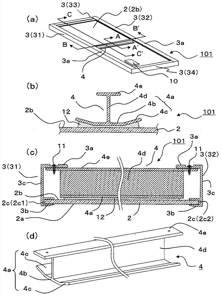
[0028] refer to Figure 1~3 The solar cell module 101 according to the first embodiment will be described.

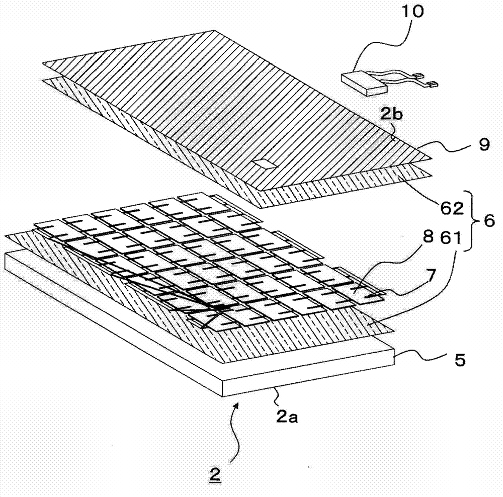
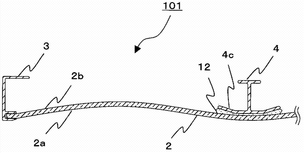
[0029] Such as figure 1 As shown in (a) and (c), the solar cell module 101 is basically a module including, for example, a rectangular solar cell panel 2 in plan view, a holding member 3 for holding the peripheral portion of the solar cell panel 2 , and a reinforcing member 3 . The holding member 3 includes, for example, a first holding member 31 for holding a pair of side portions 2c (first side portion 2c1, second side portion 2c2) of the solar cell panel 2 substantially parallel to each other, a second holding member 32, and a solar cell panel holding member. The third holding member 33 and the fourth holding member 34 of the other pair of side portions of the 2 are substantially parallel to each other. It should be noted that the solar cell module 101 may also have a terminal box 10 for taking out the output of the solar cell panel 2 on the non-light-receiving sur...

no. 2 approach

[0059] Below, refer to Figure 5 The solar cell module 102 according to the second embodiment of the present invention will be described.

[0060] In the solar cell module 102 according to this embodiment, the shape of the reinforcement member 4 is different from that of the solar cell module 101 according to the first embodiment. Specifically, as Figure 5 As shown, the reinforcing member 4 further has a connecting portion 4f connecting the horizontal portion 4b and the inclined portion 4c. Moreover, the thickness of this connection part 4f is smaller than the thickness of the horizontal part 4b, and it is also smaller than the thickness of the inclined part 4c. That is, the reinforcing member 4 is different from the first embodiment in that the connecting portion between the horizontal portion 4b and the inclined portion 4c is thin and easily bendable.

[0061] This way, for example Figure 5 As shown, it is only necessary to form a notch on the non-light-receiving surfa...

no. 3 approach

[0066] Below, refer to Figure 6 The solar cell module 103 according to the third embodiment of the present invention will be described. The solar cell module 103 according to this embodiment differs from the first embodiment in the shape of the reinforcing member 4 .

[0067] Specifically, as Figure 6 As shown, in the solar cell module 103 according to this embodiment, the thickness of the inclined portion 4c is smaller than the thickness of the horizontal portion 4b. It should be noted that, similarly to the second embodiment, it can also be said that the connecting portion between the horizontal portion 4b and the inclined portion 4c is thinned. That is, in this embodiment, there is a shape in which the plate thickness of the support part 4a becomes thinner ahead from the connection part of the horizontal part 4b and the inclined part 4c.

[0068] In such an aspect, as in the second embodiment, bending tends to occur at the connection portion between the horizontal port...


PUM


Abstract

A solar cell module (101) of the present invention is provided with: a solar cell panel (2) having a light reception surface (2a), a light non-reception surface (2b), and a first side part (2c1) and a second side part (2c2) which are located between the light reception surface and the light non-reception surface and which do not lie in the same plane; a first holding member (31) which holds the first side part of the solar cell panel; a second holding member (32) which holds the second side part of the solar cell panel; and a longitudinal reinforcement member (4) which is installed between the first holding member and the second holding member on the side of the light non-reception surface. The reinforcement member comprises a support section (4a) which supports the light non-reception surface of the solar cell panel, and the support section comprises a horizontal section (4b) parallel to the light non-reception surface, and an inclined section (4c) which is located on the end side of the horizontal section and is inclined so that the farther it is from the horizontal section, the more distant it is from the light non-reception surface. The reinforcement member is secured to the solar cell panel by an adhesive (12) on the horizontal section and the inclined section. Because the thickness of the adhesive at the end of the inclined section is thick, there are effects that deformation of the solar cell in the compressed direction easily occurs, and the shearing stress applied to the solar cell by the outer edge of the reinforcement member can be reduced.

Description

technical field [0001] The present invention relates to solar cell modules. Background technique [0002] With the strengthening of environmental protection trends in recent years, solar photovoltaic power generation systems with less environmental burdens are attracting attention. Furthermore, in order to popularize and expand such a solar photovoltaic power generation system, it is necessary to increase the productivity of solar cell modules constituting the solar photovoltaic power generation system. [0003] As one means of improving the productivity of solar cell modules, there is an increase in the size of solar cell modules. By increasing the size of the solar cell module, it is possible to reduce the manufacturing time per unit area and the like. However, since the area of ​​the large-sized solar cell module becomes larger, it is in a state of receiving a large wind load and snow load, and damage to the solar cell module is likely to occur. [0004] In order to so...

Claims


Application Information

Patent Timeline
Patent Type & Authority Applications(China)
IPC IPC(8): H01L31/042
CPCH02S30/10Y02E10/47F24S2080/09F24S25/30F24S2025/016F24S2025/601F24S2025/806Y02E10/50
Inventor 山下满雄户田和秀隅田健一郎
Owner KYOCERA CORP
Why Eureka
Try Eureka