

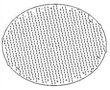
Method for producing millimeter wave antenna slot array sheet
A millimeter-wave antenna and slot array technology, which is applied in the direction of manufacturing tools, milling machine equipment details, metal processing equipment, etc., can solve the problems of processing deformation, poor rigidity, cutting vibration, etc., to balance residual stress, avoid breaking accidents, and prevent assembly The effect of clip deformation
- Summary
- Abstract
- Description
- Claims
- Application Information
AI Technical Summary
Problems solved by technology
Method used
Image

Examples
Embodiment Construction
[0023] based on the following figure 2 and image 3 Preferred embodiments of the present invention will be described in detail.
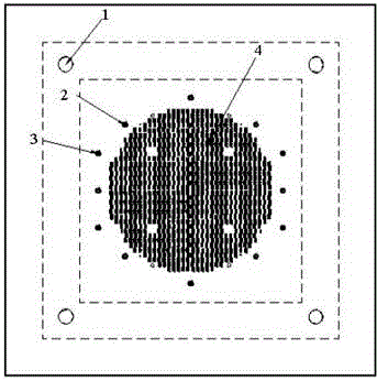
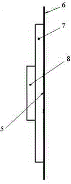
[0024] The invention provides a method for manufacturing a thin plate of a millimeter wave antenna slot array, such as figure 2 and image 3 As shown, the manufacturing method includes the following steps:
[0025] Step 1, making the tooling substrate 7, setting a number of positioning holes on the upper surface of the tooling substrate as a benchmark for subsequent processes;
[0026] In this embodiment, the tooling substrate adopts a 3R transfer aluminum plate 7;
[0027] Step 2, process the positioning pin hole 3 and the compression screw hole 2 at the position of the positioning hole set in step 1, as the position reference of the subsequent process;
[0028] In this embodiment, 4 positioning pin holes 3 and 8 compression screw holes 2 are processed;
[0029] Step 3. Clamp the upper platen 6 on the surface of the tooling base plate 7. Ba...
PUM
| Property | Measurement | Unit |
|---|---|---|
| height | aaaaa | aaaaa |
Abstract
Description
Claims
Application Information