Energy-saving combination power system of engine of automobile

An automobile engine and combined power technology, which is applied to vehicle components, auxiliary drive devices, control devices, etc., can solve the problems of unutilized sliding inertia energy, shortening the sliding distance of the car, and low conversion efficiency, so as to increase and reduce the sliding distance. The effect of reducing energy consumption and drag resistance

Inactive Publication Date: 2013-10-02
蒋万文
View PDF0 Cites 3 Cited by
  • Summary
  • Abstract
  • Description
  • Claims
  • Application Information

AI Technical Summary

Problems solved by technology

[0002] At present, the transmission sequence of the known traditional internal combustion engine power vehicles is the engine, clutch, transmission to the drive axle. Due to the undulating factors of the road and the complex road conditions in the operation of the vehicle, especially the rapid development of high-grade roads, modern vehicles have problems in operation. In a large number of gliding conditions, the drag resistance generated by the engine during gliding shortens the gliding distance of the car, especially for commercial vehicles with large engine displacement. When the engine runs at high speed to drive t

Method used


Image

  • Energy-saving combination power system of engine of automobile

Examples


Embodiment Construction

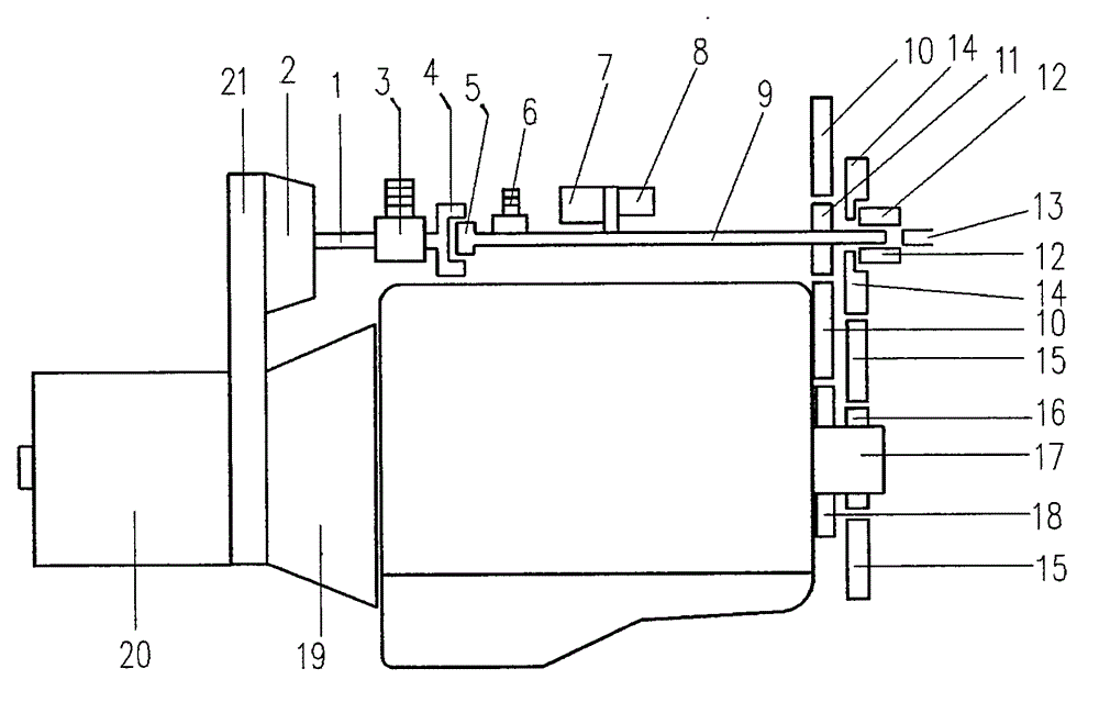
[0009] In the accompanying drawings, the power take-off device (21) is connected with the power input shaft of the transmission (20) and the power output shaft of the main clutch (19), and the power of the automobile engine can be transmitted to the secondary clutch (2) by the main clutch The power input shaft, the sliding inertial energy and the braking energy of the automobile can also be transmitted to the power input shaft of the auxiliary clutch (2) by the power input shaft of the transmission (20). When the automobile engine accelerates to drive the automobile, the auxiliary clutch (2) does not combine , the power is driven by the crankshaft gear (18) fixedly connected with the crankshaft (17) of the engine to drive the deceleration one-way gear driving wheel (10) to reduce the speed, and then through the deceleration one-way gear driven wheel (11) to the accessory drive shaft (9) , so that the main air compressor (6), the air conditioner compressor (7) and the generator ...


PUM


Abstract

The invention discloses an energy-saving combination power system of an engine of an automobile. The system is characterized in that an auxiliary clutch is arranged between a main clutch of the automobile and a speed changer; the main clutch is separated and the auxiliary clutch is combined when the automobile decelerates and slides; a primary air compressor, a driving wheel of a high-speed one-way gear and a driven wheel of the high-speed one-way gear are driven to a main air compressor, an air conditioning compressor and a power generator which are connected with an accessory transmission shaft by sliding inertia energy of the automobile to allow the main air compressor, the air conditioning compressor and the power generator to operate at a high speed for converting energy of the engine; power of the engine is transmitted to a sliding sleeve gear, a speed reducing gear, a driving wheel of a crankshaft one-way gear and a driven wheel of the crankshaft one-way gear which are connected with the accessory transmission shaft to drive an engine crankshaft to operate at a low speed, so that dragging resistance when the engine operates passively is reduced. When the engine accelerates to operate to drive the automobile, the auxiliary clutch is separated, the power of the engine is reduced by a crankshaft gear, a driving wheel of a speed reducing one-way gear, and a driven wheel of the speed reducing one-way gear, and then drives related accessories connected with the accessory transmission shaft to operate at a low speed, so that power consumption of the engine is reduced.

Description

Technical field [0001] The invention relates to an energy-saving combined power system which utilizes the sliding inertia and braking energy of the automobile to reduce the power consumption of engine accessories and reduce the drag resistance of the automobile engine. Background technique [0002] At present, the transmission sequence of the known traditional internal combustion engine power vehicles is the engine, clutch, transmission to the drive axle. Due to the undulating factors of the road and the complex road conditions in the operation of the vehicle, especially the rapid development of high-grade roads, modern vehicles have problems in operation. In a large number of gliding conditions, the drag resistance generated by the engine during gliding shortens the gliding distance of the car, especially for commercial vehicles with large engine displacement. When the engine runs at high speed to drive the vehicle, its air compressor, air conditioner The high-speed operati...

Claims


Application Information

Patent Timeline
IPC IPC(8): B60K25/10B60K17/00
Inventor 蒋万文
Owner 蒋万文
Why Eureka
Try Eureka