Roadbed subsidence grouting treatment structure and construction method thereof

A technology for controlling structure and roadbed, applied in the field of roadbed subsidence grouting treatment structure and construction, can solve the problems of roadbed subsidence, affecting roadbed stability, water can not be discharged in time, etc., achieving simple construction technology, ensuring grouting effect, and ensuring roadbed strength. Effect

Active Publication Date: 2013-10-02
CENT SOUTH UNIV
View PDF5 Cites 11 Cited by
  • Summary
  • Abstract
  • Description
  • Claims
  • Application Information

AI Technical Summary

Problems solved by technology

However, the traditional subsidence grouting treatment structure and construction method have the following defects: First, when multiple grouting pipes are driven into the roadbed, it is impossible to grout the multiple grouting pipes at the same time, so the grouting pressure of each grouting pipe , grouting duration, etc. cannot be guaranteed to be the same, which will cause different grouting effects of each grouting pipe, uneven subsidence and uplift of the subgrade, etc.
Secondly, the traditional construction method does not set seepage ditches after the grouting is completed, so that the water in the subgrade cannot be discharged in time after precipitation, and the infiltration of precipitation will soften the subgrade, affect the stability of the subgrade and cause subsidence of the subgrade

Method used


Image

  • Roadbed subsidence grouting treatment structure and construction method thereof
  • Roadbed subsidence grouting treatment structure and construction method thereof

Examples


Embodiment 1

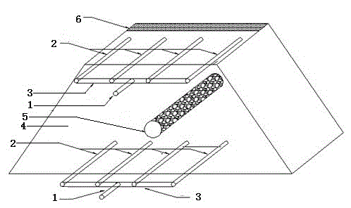
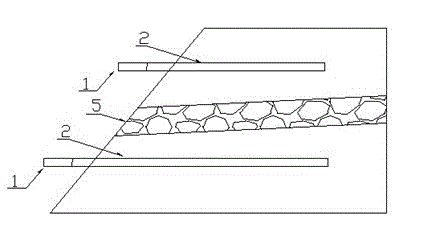
[0018] see figure 1 and figure 2 , the roadbed subsidence grouting treatment structure includes two rows of grouting pipes arranged on both sides of the central divider 6 and horizontally inserted into the roadbed 4 from the outside of the roadbed 4, each row of grouting pipes includes several grouting pipes 2, One end of several grouting pipes 2 in the same row exposed outside the subgrade 4 communicates with one side of the same connecting pipe 3, and the other side of the connecting pipe 3 communicates with the main grouting pipe 1; There is a drainage ditch 5 in the same direction as the grouting pipe 2.

[0019] Wherein, the drainage ditch 5 is filled with stones. The drainage ditch 5 is inclined from the central partition 6 to the outer edge of the roadbed 4 . The slope of the drainage ditch 5 is ≥2%, preferably 10%. The grouting pipe 2 is a grouting steel flower pipe; the grouting main pipe 1 and the connecting pipe 3 are both steel pipes. Each row of grouting pip...

Embodiment 2

[0021] The construction subgrade is 8m high, and the horizontal grouting is carried out vertically in two layers, that is, the horizontal flower tube grouting is carried out from the top surface of the subgrade 2m and 5m respectively, and four grouting tubes are arranged in each layer with a spacing of 3m. Four grouting pipes are led out of the side slope by a main grouting pipe to facilitate grouting. The length of the upper grouting pipe is 16.9m, and the length of the lower grouting pipe is 21.5m. Between the two layers of horizontal grouting flower tubes, a drainage seepage ditch is laid 3.5m away from the top surface of the subgrade. The cross section of the seepage ditch is circular with a diameter of 2m, filled with gravel, and slopes from the central separation zone to the outer edge of the slope with a slope of 10% to facilitate water discharge.

[0022] The construction method of the subsidence grouting treatment structure of the subgrade:

[0023] (1) Place remind...


PUM


Abstract

The invention discloses a roadbed subsidence grouting treatment structure and a construction method thereof. The roadbed subsidence grouting treatment structure comprises a plurality of rows of grouting pipe groups which are arranged on both sides of a central division strip of a roadbed and inserted at the interior of the roadbed horizontally from the outer side of the roadbed, wherein each row of grouting pipe groups comprise a plurality of grouting pipes; a plurality of grouting pipes in the same row are exposed at one end of the outer side of the roadbed and are communicated with one side of a same connecting pipe; the other side of the connecting pipe is communicated with a grouting main pipe; and drainage sewers in the same direction as the grouting pipes are arranged between two adjacent rows of grouting pipe groups. The grouting effect of a plurality of grouting pipes can be ensured, and accumulated water in the roadbed is drained in time; and moreover, the construction technology is simple, and the manufacturing cost is low.

Description

technical field [0001] The invention relates to a roadbed subsidence grouting treatment structure and a construction method. Background technique [0002] Subgrade is an important structural facility of a highway, and it is also one of the important contents of highway maintenance. Engineering practice shows that grouting reinforcement method is one of the effective methods to deal with subgrade settlement diseases. However, the traditional subsidence grouting treatment structure and construction method have the following defects: First, when multiple grouting pipes are driven into the roadbed, it is impossible to grout the multiple grouting pipes at the same time, so the grouting pressure of each grouting pipe , grouting duration, etc. cannot be guaranteed to be the same, which will cause problems such as different grouting effects of each grouting pipe, and uneven subsidence and uplift of the subgrade. Secondly, the traditional construction method does not set seepage di...

Claims


Application Information

Patent Timeline
Patent Type & Authority Applications(China)
IPC IPC(8): E01C23/10E01F5/00
Inventor 邹金锋童无欺曾胜赵炼恒李振存李文刘晖峻张淼
Owner CENT SOUTH UNIV
Why Eureka
Try Eureka